Efficient seawater desalting plant

A water collecting device and high-efficiency technology, which are applied in seawater treatment, general water supply conservation, chemical instruments and methods, etc., can solve the problems of large volume, low seawater desalination rate and efficiency, and high energy consumption, and achieve small thermal resistance and appearance. Small structure, the effect of improving heat exchange efficiency and speed

Pending Publication Date: 2016-12-14
朱文通
View PDF3 Cites 5 Cited by
  • Summary
  • Abstract
  • Description
  • Claims
  • Application Information

AI Technical Summary

Problems solved by technology

[0011] The purpose of the present invention is to overcome the disadvantages of large volume, high energy consumption, and low seawater desalination rate and efficiency of the low-temperature multi-effect seawater desalination device in the prior art

Method used


Image

  • Efficient seawater desalting plant
  • Efficient seawater desalting plant
  • Efficient seawater desalting plant

Examples


Embodiment 1

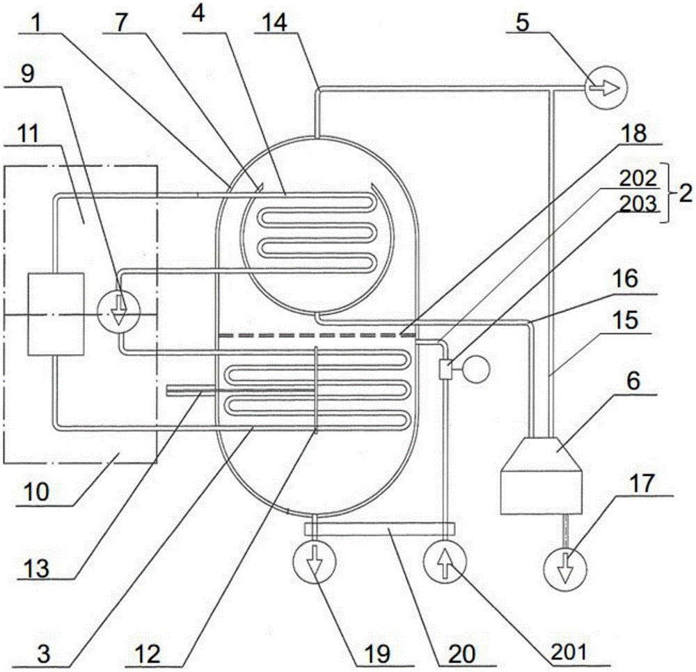
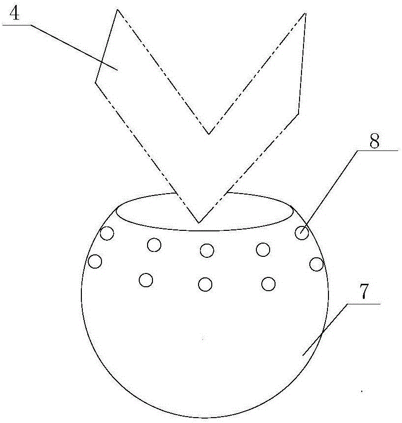
[0035] Such as figure 1 and figure 2 As shown, the present invention discloses a high-efficiency seawater desalination device, including a shell 1, a water injection device 2, an evaporator 3, a condenser 4, a vacuum device 5 and a water collection device 6, and the vacuum device 5 passes through a first The vacuum pipeline 14 communicates with the housing 1, and communicates with the water collecting device 6 through the second vacuum pipeline 15. The vacuum device 5 is a water jet extractor, a steam jet extractor, a vane vacuum pump or a vacuum pump. One of the vacuum pumps, the vacuum device 5 continuously discharges the partially condensed gas in the casing 1 and the water collecting device 6 and maintains a high vacuum state of the two.

[0036] The housing 1 is divided into two cavities connected up and down, the condenser 4 and the evaporator 3 are respectively arranged in the upper and lower cavities of the housing 1, the evaporator 3, the evaporator 3 The condenser...

Embodiment 2

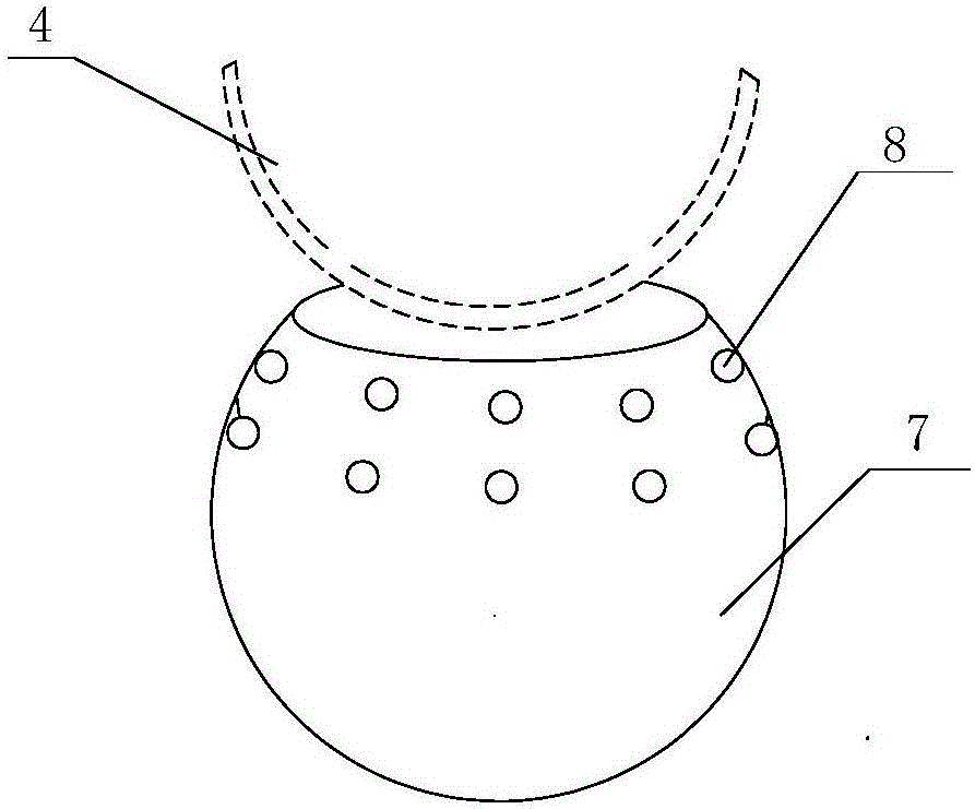
[0049] Such as figure 1 and image 3 As shown, the present invention discloses a high-efficiency seawater desalination device, including a shell 1, a water injection device 2, an evaporator 3, a condenser 4, a vacuum device 5 and a water collection device 6, and the vacuum device 5 passes through a first The vacuum pipeline 14 communicates with the housing 1, and communicates with the water collecting device 6 through the second vacuum pipeline 15. The vacuum device 5 is a water jet extractor, a steam jet extractor, a vane vacuum pump or a vacuum pump. One of the vacuum pumps, the vacuum device 5 continuously discharges the partially condensed gas in the casing 1 and the water collecting device 6 and maintains a high vacuum state of the two.

[0050] The housing 1 is divided into two cavities connected up and down, the condenser 4 and the evaporator 3 are respectively arranged in the upper and lower cavities of the housing 1, the evaporator 3, the evaporator 3 The condenser ...


PUM


Abstract

The invention discloses an efficient seawater desalting plant which comprises a housing and a vacuum pumping device, wherein the vacuum pumping device is used for pumping the housing vacuum; the housing is divided into an upper cavity and a lower cavity which are communicated; the housing is provided with a condenser in the upper cavity, and an evaporator in the lower cavity; the evaporator, the condenser and a heat compression unit form a heat circulation system; the upper cavity of the housing is further internally provided with a condenser collection box; the top part of the condenser collection box is opened; the condenser is arranged above the condenser collection box; and the condenser collection box is used for collecting fresh water produced after condensation. The efficient seawater desalting plant is small in size; the seawater is desalted in the phase transition transfer of the moisture from evaporation to condensation by utilizing the high thermal conductivity, the isothermality and the sensibility of the phase transition temperature of the moisture of the seawater at the high vacuum state as well as the special structures of the condenser and the condenser collection box, so that the desalting speed and the desalting efficiency of the seawater are improved, and the efficient seawater desalting plant has very high energy-saving and environment-protecting values.

Description

technical field [0001] The invention relates to the field of seawater desalination treatment, in particular to an efficient seawater desalination device. Background technique [0002] Water resources are basic natural resources and strategic economic resources. The sustainable utilization of water resources is a major strategic issue related to economic and social development. Of the total water resources on the earth, fresh water accounts for only 2.5%, and seawater accounts for 97.5%. Seawater utilization is one of the important measures for human society to solve the water resource crisis. [0003] At the end of the 16th century, humans began to use distillers to directly evaporate seawater on board to produce fresh water. At the end of the 19th century, with the appearance of steam ships, evaporator distilled water was also born to meet the supply of ship boilers and drinking water. Multi-stage flash evaporation technology appeared in the 1950s. In the 1960s, the Unite...

Claims


Application Information

Patent Timeline
Patent Type & Authority Applications(China)
IPC IPC(8): C02F1/04B08B9/023C02F103/08
CPCC02F1/04B08B9/023C02F2103/08Y02A20/124
Inventor 朱文通
Owner 朱文通
Why Eureka
Try Eureka