A low-quality waste heat utilization system in a steel plant and its application method

A low-quality, steel plant technology, applied in chemical instruments and methods, general water supply conservation, water/sludge/sewage treatment, etc. The effect of reducing overall energy consumption and pollutant emissions

Active Publication Date: 2020-03-27
SHOUGANG JINGTANG IRON & STEEL CO LTD
View PDF1 Cites 0 Cited by
  • Summary
  • Abstract
  • Description
  • Claims
  • Application Information

AI Technical Summary

Problems solved by technology

[0003] Aiming at the problem of low utilization rate of low-quality waste heat in iron and steel plants in the above-mentioned prior art, the present invention provides a low-quality waste heat utilization system and its application method in iron and steel plants, using low-quality waste heat such as blast furnace slag flushing water and flue gas waste heat in iron and steel plants The heat source replaces the heat source of low-temperature multi-effect seawater desalination, which effectively utilizes waste heat and reduces the cost of low-temperature multi-effect seawater desalination production

Method used


Image

  • A low-quality waste heat utilization system in a steel plant and its application method
  • A low-quality waste heat utilization system in a steel plant and its application method
  • A low-quality waste heat utilization system in a steel plant and its application method

Examples


Embodiment 1

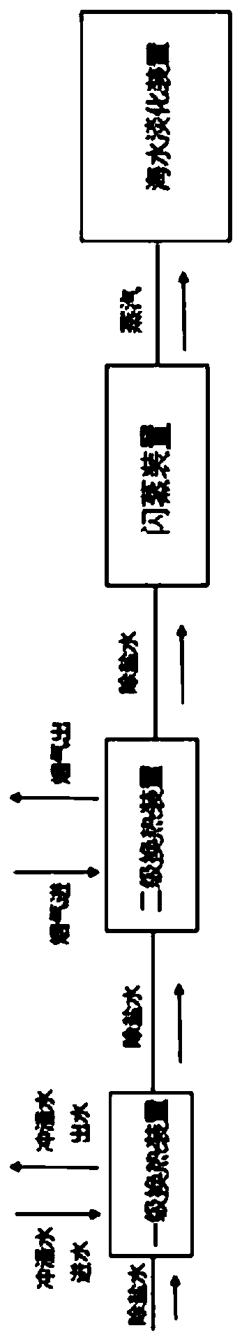
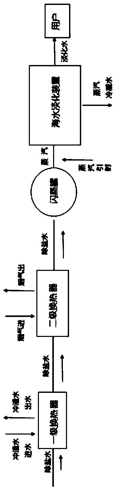
[0040] like figure 2 As shown, the low-quality waste heat utilization system of the iron and steel plant in Embodiment 1 of the present invention includes:

[0041] A primary water-to-water heat exchanger for transferring heat between a first fluid and a second fluid, the primary water-to-water heat exchanger comprising: a first channel fluid passage for the first fluid, the A first channel fluid passage is provided with a first inlet and a first outlet; and a second channel fluid passage for a second fluid is provided with a second inlet and a second outlet, the first and The fluid passages of the second channel are adjacently arranged, and the first inlet, the first outlet, the second inlet and the second outlet are separately arranged at the end of the first-stage water-water heat exchanger, and the first fluid is brine, the second fluid is blast furnace slag flushing water;

[0042] The secondary air-water heat exchanger and the primary water-water heat exchanger are us...

Embodiment 2

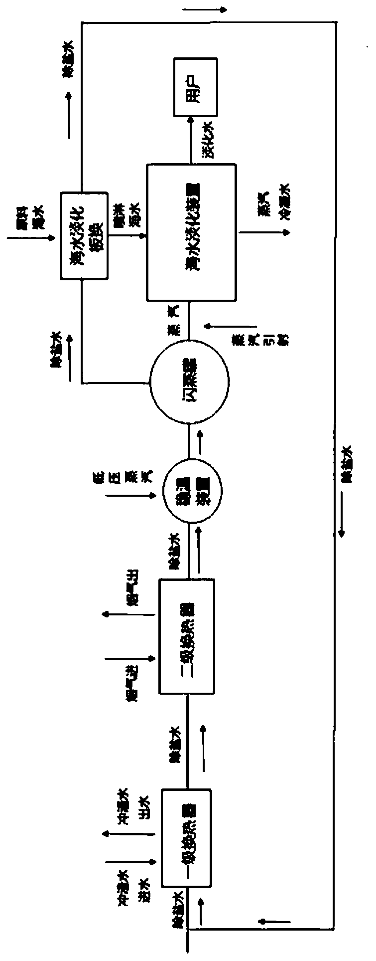
[0047] like image 3 As shown, the low-quality waste heat utilization system of the iron and steel plant in Embodiment 2 of the present invention includes:

[0048] A primary water-to-water heat exchanger for transferring heat between a first fluid and a second fluid, the primary water-to-water heat exchanger comprising: a first channel fluid passage for the first fluid, the A first channel fluid passage is provided with a first inlet and a first outlet; and a second channel fluid passage for a second fluid is provided with a second inlet and a second outlet, the first and The fluid passages of the second channel are adjacently arranged, and the first inlet, the first outlet, the second inlet and the second outlet are separately arranged at the end of the first-stage water-water heat exchanger, and the first fluid is brine, the second fluid is blast furnace slag flushing water;

[0049] The secondary air-water heat exchanger and the primary water-water heat exchanger are use...


PUM


Abstract

The invention provides an iron and steel plant low-quality waste heat utilization system and a using method thereof. The system comprises a primary heat exchange device for transferring heat between a first fluid and a second fluid, a secondary heat exchange device for transferring heat between a third fluid and a fourth fluid and a flash evaporation device, wherein the first fluid is demineralized water, the second fluid is blast furnace slag flushing water, the third fluid is demineralized water flowing out of the primary heat exchange device, the fourth fluid is high-temperature smoke, the flash evaporation device is communicated with the secondary heat exchange device, and the demineralized water from the secondary heat exchange device enters the flash evaporation device to be converted into steam serving as a heat source of a sea water desalination device so as to obtain sea water distilled water through evaporation. The system adopts blast furnace slag flushing water, smoke waste heat and other low-quality heat sources of an iron and steel plant to replace a heat source for low-temperature multi-effect sea water desalination, effectively utilizes waste heat and reduces the production cost for low-temperature multi-effect sea water desalination.

Description

technical field [0001] The invention belongs to the technical field of waste heat recovery, and in particular relates to a low-quality waste heat utilization system in a steel plant and a method for using the same. Background technique [0002] At present, the recycling rate of waste heat and waste energy in the iron and steel industry is low. The low-temperature waste heat accounts for about 35% of the total waste heat, and the recovery rate is almost zero. recovery potential. During the ironmaking process of the blast furnace, the slag flushing water absorbs the heat of the iron slag and discharges it into the atmosphere through the cooling tower, resulting in a waste of energy. At present, the recovery of waste heat from the slag flushing water in steel plants is mainly reflected in winter heating, but the large amount of slag flushing water contains The heat is very large, and the heating load of general factory office buildings is small, and the waste heat capacity of ...

Claims


Application Information

Patent Timeline
Patent Type & Authority Patents(China)
IPC IPC(8): C02F1/16C02F103/08
CPCC02F1/16C02F2103/08Y02A20/124
Inventor 吴刚吴礼云王铁民王涛唐志新张波孙雪
Owner SHOUGANG JINGTANG IRON & STEEL CO LTD
Why Eureka
Try Eureka