Centrifugal-type small part hot galvanizing system with parts

A centrifugal, small parts technology, applied in hot dip plating process, coating, metal material coating process, etc., can solve the problems of discount of centrifugal effect, reduced production efficiency, fast solidification speed of zinc liquid, etc., to achieve energy saving and consumption reduction Significantly, improve production efficiency, good galvanizing effect

Active Publication Date: 2016-12-14
嘉兴宝利机械股份有限公司
View PDF6 Cites 13 Cited by
  • Summary
  • Abstract
  • Description
  • Claims
  • Application Information

AI Technical Summary

Problems solved by technology

[0003] At present, in the hot-dip galvanizing production line for small parts, multiple barrels containing parts to be processed are usually moved synchronously on the conveying track, passing through the feeding area, galvanizing area, centrifugal area and discharging area in sequence, in order to ensure the galvanized The quality needs to ensure the effective reaction time of the barrel in the zinc liquid pool, so the speed of the track rotation is relatively slow. Since all the barrels move synchronously with the track, the speed of the track remains the same throughout the process, and it is impossible to complete the galvanized single The speed of the barrel is controlled, which results in a long time for the barrel to move from the centrifugal area to the discharge area. The long-term transportation process makes the temperature of the barrel plummet, and the zinc liquid in the barrel is also transformed from liquid to solid. After the barrel is unloaded in the discharge area, when it enters the feed area again, the barrel must be heated to about 530°C, which increases the heating time and energy consumption, and the whole process takes a long time. low work efficiency
[0004] When the workpieces to be processed enter the galvanizing area for galvanizing procedures, it is inevitable that impurities will be brought into the zinc liquid poo

Method used


Image

  • Centrifugal-type small part hot galvanizing system with parts
  • Centrifugal-type small part hot galvanizing system with parts
  • Centrifugal-type small part hot galvanizing system with parts

Examples


Example Embodiment

[0043] In order to enable those skilled in the art to better understand the solutions of the present invention, the technical solutions in the embodiments of the invention will be clearly and completely described below in conjunction with the drawings in the embodiments of the present invention. Obviously, the described embodiments are only It is a part of embodiments of the present invention, but not all embodiments. Based on the embodiments of the present invention, all other embodiments obtained by persons of ordinary skill in the art without making creative efforts shall fall within the protection scope of the present invention.

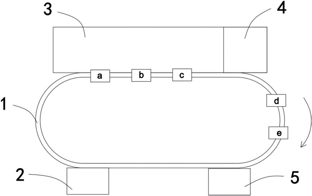
[0044] refer to figure 1As shown, a hot-dip galvanizing system for centrifugal small parts with parts includes a track mechanism 1 with a ring-shaped track structure, and a feeding area 2, a galvanizing area 3, a centrifugal area 4 and an outlet area arranged along the periphery of the track mechanism 1 In the material area 5, at least two feedi...


PUM


Abstract

The invention discloses a centrifugal-type small part hot galvanizing system with parts. The hot galvanizing system comprises a track mechanism, a feeding area, a galvanizing area and a discharging area, wherein the feeding area, the galvanizing area and the discharging area are arranged along the track mechanism. The track mechanism is movably provided with at least two feeding mechanisms. A centrifugal area is arranged at the terminal of the galvanizing area. The centrifugal area comprises centrifugal equipment and a grabbing mechanism. The grabbing mechanism can transfer charging baskets containing the parts to be machined to the grabbing mechanism from the feeding mechanisms for centrifugal galvanizing. According to the hot galvanizing system, the galvanizing area and the centrifugal area are adjacently arranged, the structure is simplified, and the galvanized machined parts can enter the centrifugal area at once for centrifugal galvanizing. The galvanizing effect is good, the process of repeatedly heating molten zinc to a designated temperature is omitted, and the energy-saving and cost-reducing effects are obvious. Moreover, the phenomenon that the galvanizing effect is influenced due to the fact that the machined parts are polluted when being transferred to the centrifugal area from the galvanizing area is avoided, so that production efficiency is improved, the coating quality is good and safety performance is high.

Description

technical field [0001] The invention belongs to the field of hot-dip galvanizing, in particular to a centrifugal type hot-dip galvanizing system for small parts with parts. Background technique [0002] In order to ensure the aesthetics and rust resistance of metals, alloys and other materials, hot-dip galvanizing is usually performed on the surface of the material. Hot-dip galvanizing is also called hot-dip galvanizing and hot-dip galvanizing. It is an effective metal anti-corrosion method. It immerses the pre-treated material in a molten zinc solution at about 530°C. After complex physical and chemical actions, a zinc layer is attached to the surface of the material to achieve the purpose of anti-corrosion. [0003] At present, in the hot-dip galvanizing production line for small parts, multiple barrels containing the parts to be processed are usually moved synchronously on the conveying track, passing through the feeding area, galvanizing area, centrifugal area and disch...

Claims


Application Information

Patent Timeline
IPC IPC(8): C23C2/14C23C2/06
CPCC23C2/003C23C2/06C23C2/14
Inventor 陆军明陆振飞居靖杰陆敏佳
Owner 嘉兴宝利机械股份有限公司
Why Eureka
Try Eureka