Multi-main grid double-sided solar battery assembly

A double-sided solar cell and multi-busbar technology, applied in electrical components, circuits, photovoltaic power generation, etc., can solve problems such as desoldering, increase component cost, and reduce component light transmittance, so as to reduce production cost and contact resistance , The effect of improving reliability and power generation efficiency

Inactive Publication Date: 2016-12-14
LIANYUNGANG SHENZHOU NEW ENERGY
View PDF6 Cites 12 Cited by
  • Summary
  • Abstract
  • Description
  • Claims
  • Application Information

AI Technical Summary

Problems solved by technology

[0005] 1) The outer layer of the metal wire needs to be wrapped with a layer of low-temperature alloy. This technology is immature and will increase the cost of the metal wire;
[0006] 2) It needs to be fixed with an adhesive film, which will reduce the light transmittance of the module, increase the cost of the module, and affect the reliability of the module;
[0007] 3) The contact area between the metal wire and the auxiliary grid line is small, and the change of temperature difference is easy to cause desoldering;
[0008] 4) It is easy to produce offset during lamination
[0009] 2. "Passive film fixation method" puts the metal wire between the silicon wafer and the passivation film of the solar cell. Although it effectively solves the problems of welding offset and other problems, the coating technology in this technology is difficult, and it is currently difficult to batch Production
[0010] 3. The "U-shaped wire method" adopts a U-shaped wire structure (U-shaped wire method), which solves the problem that the wire is easy to bend to a certain extent, but there will also be deviations and weak welding. The silk process is also more complex

Method used


Image

  • Multi-main grid double-sided solar battery assembly
  • Multi-main grid double-sided solar battery assembly
  • Multi-main grid double-sided solar battery assembly

Examples


Embodiment Construction

[0040] The present invention will be further explained below in conjunction with the accompanying drawings and specific embodiments. It should be understood that the following specific embodiments are only used to illustrate the present invention and are not intended to limit the scope of the present invention. It should be noted that the words "front", "rear", "left", "right", "upper" and "lower" used in the following description refer to the directions in the drawings, and the words "inner" and "outer ” refer to directions towards or away from the geometric center of a particular part, respectively.

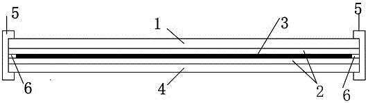
[0041] like figure 1 As shown, the module body of the present invention includes the front film 1, the multi-busbar double-sided solar cell group 3 and the back film 4, and the multi-busbar double-sided solar cell group 3 is arranged on the front film 1 and the back film Between 4, an encapsulation film 2 is provided between the multi-busbar double-sided solar cell group 3 and...


PUM


Abstract

The invention discloses a multi-main grid double-sided solar battery assembly, which comprises an assembly body which comprises a front film, a double-sided solar battery pack and a back film, wherein the double-sided solar battery pack is arranged between the front film and the back film; packaging adhesive films are arranged between the double-sided solar battery pack and the front film and between the double-sided solar battery pack and the back film; the double-sided solar battery pack comprises a plurality of multi-main grid double-sided solar battery pieces and metal wires; the metal wires extend between the adjacent battery pieces to achieve electric connection; a silicon substrate is arranged in the middle of each multi-main grid double-sided solar battery piece; 10-25 main grid lines and 70-500 secondary grid lines are arranged on the front surface and the reverse surface of each silicon substrate; the main grid lines are vertical to the secondary grid lines; welding spots are arranged on intersection points of the main grid lines and the secondary grid liens at intervals; and silver connection lines are arranged among the welding spots of the main grid lines. The contact resistance of the metal wires and the battery pieces can be reduced by optimizing the main grid line design of double-sided solar batteries; the offset problem in welding of a plurality of main grid lines is solved; the reliability and the power generation efficiency of the battery assembly are improved; and the production cost of the assembly is reduced.

Description

technical field [0001] The invention belongs to the technical field of photovoltaic modules, and in particular relates to a multi-busbar double-sided solar battery module. Background technique [0002] At present, the number of main grids of the mainstream crystalline silicon solar cell modules on the market is generally 3 grids, which are usually realized by automatic welding. From 3 to 4 or even 5, and in 2007, Day4 Energy technology proposed the idea of ​​busbar-free solar cells. This technology no longer prints busbars on solar cells, but uses multiple metal wires ( ≥10 pieces) instead of conventional soldering ribbons, while improving the cell efficiency (≥0.3%), it saves the amount of silver paste (≥30%) and reduces the cost of solar cells. The double-sided solar cells produced now , it can receive light and generate electricity on both sides. In addition to the power that can be output on the front side, the back side can also convert reflected, scattered or irradiat...

Claims


Application Information

Patent Timeline
Patent Type & Authority Applications(China)
IPC IPC(8): H01L31/0224
CPCH01L31/022433Y02E10/50
Inventor 陈喜平秦涛涛张昌远张龙龙李金欣林佳继张忠卫石磊
Owner LIANYUNGANG SHENZHOU NEW ENERGY
Why Eureka
Try Eureka