High-efficient rectification antenna based on microwave RFID frequency range low-power input

A rectenna, low-power technology, applied in antennas, antenna parts, antenna supports/installation devices, etc., can solve the problems of low operating frequency, low conversion efficiency, and large size of rectennas, and achieve easy promotion and energy conversion. High efficiency and high frequency effect

Inactive Publication Date: 2016-12-14
SUN YAT SEN UNIV +1
View PDF6 Cites 9 Cited by
  • Summary
  • Abstract
  • Description
  • Claims
  • Application Information

AI Technical Summary

Problems solved by technology

[0004] However, the traditional rectenna has low operating frequency, large volume, difficult in

Method used


Image

  • High-efficient rectification antenna based on microwave RFID frequency range low-power input
  • High-efficient rectification antenna based on microwave RFID frequency range low-power input
  • High-efficient rectification antenna based on microwave RFID frequency range low-power input

Examples


Example Embodiment

[0029] Example 1

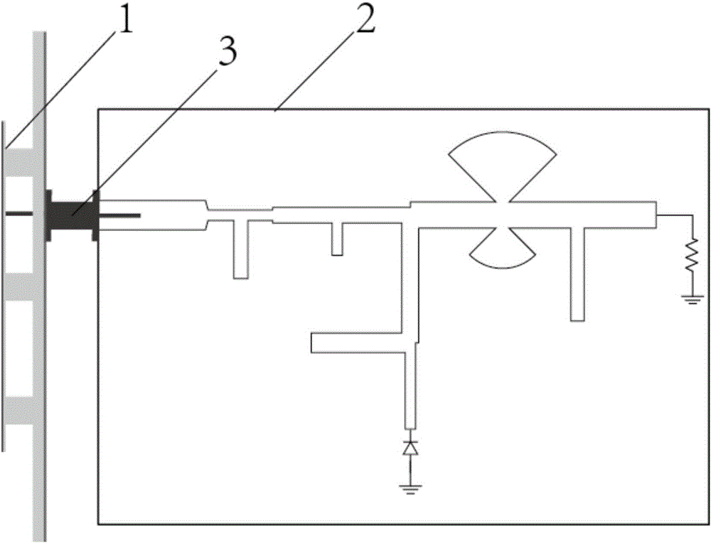
[0030] like figure 1 As shown, the rectenna includes a microstrip receiving antenna 1 and a microstrip rectifying circuit 2 , which are connected through a joint 3 . When microwaves in the RFID frequency band are transmitted to the microstrip receiving antenna 1 , the microstrip receiving antenna 1 can receive microwave energy and transmit the microwave energy to the microstrip rectifier circuit 2 through the connector 3 .

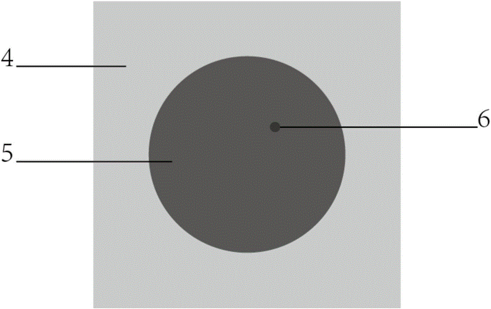
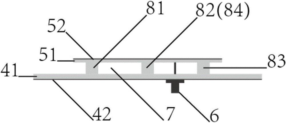
[0031] like figure 2 , 3 As shown, the microstrip receiving antenna 1 includes a floor 4, a radiation plate 5, a pillar 8 and an SMA head 6 for coaxial feeding. The gap 7 exists, the floor 4 is connected to the radiation board 5 through the pillar 8; the SMA head 6 of the coaxial feed passes through the floor 4 and connects to the radiation board 5

[0032] like image 3 As shown, the floor 4 includes a dielectric layer 41 and a copper clad layer 42, and the bottom surface of the dielectric layer 41 is attached to the top surface o...


PUM

PropertyMeasurementUnit
Thicknessaaaaaaaaaa
Radiusaaaaaaaaaa
Thicknessaaaaaaaaaa

Abstract

The invention relates to a high-efficient rectification antenna based on microwave RFID frequency range low-power input. The high-efficient rectification antenna comprises a microstrip reception antenna and a microstrip rectification circuit working under the RFID frequency range, wherein the output interface point of the microstrip reception antenna is connected with the input interface point of the microstrip rectification circuit, and the microstrip rectification circuit comprises an input interface, an impedance matching circuit, a rectification circuit, an output filter and a load. The input end of the input interface is connected with the output end of the reception antenna, and the output end of the input interface is connected with the load sequentially through the impedance matching circuit, the rectification circuit and the output filter.

Description

technical field [0001] The invention relates to the technical field of wireless energy transmission, and more specifically, to a high-efficiency rectifying antenna based on low-power input in the microwave RFID frequency band. Background technique [0002] Compared with traditional wired energy transmission methods, wireless power transmission (WPT: Wireless Power Transmission) technology has incomparable advantages in many application scenarios. For example, high-power transmission scenarios such as cross-regional power transmission and outer space energy transmission, as well as low-power application scenarios such as wireless sensor power supply and internal medical equipment power supply. Among several methods of wireless power transmission, Microwave Power Transmission (MPT: Microwave Power Transmission) has the advantages of long transmission distance, high flexibility, and high integration, and has attracted great attention. Since the concept of MPT was first propose...

Claims


Application Information

Patent Timeline
IPC IPC(8): H01Q1/22H01Q23/00
CPCH01Q1/2208H01Q23/00
Inventor 谭洪舟吴宙真区俊辉谢昭家
Owner SUN YAT SEN UNIV
Why Eureka
Try Eureka