High-reliability frequency source device

A frequency source and reliability technology, applied in the field of frequency sources, can solve the problems of low reliability, high energy consumption, poor long-term stability, etc., and achieve the effect of reducing maintenance times, prolonging service life and improving reliability.

Active Publication Date: 2016-12-14
10TH RES INST OF CETC
View PDF6 Cites 10 Cited by
  • Summary
  • Abstract
  • Description
  • Claims
  • Application Information

AI Technical Summary

Problems solved by technology

The oscillation frequency of ordinary clocks will change slightly, resulting in inaccurate time, while atomic clocks can obtain extremely high time accuracy due to the use of atomic oscillation frequencies
Atomic clocks are extremely precise timers made of the stable oscillation frequency of cesium, rubidium and other atoms, with high accuracy. However, due to the large size of atomic clocks, high energy consumption, high environmental requirements, low reliability, and must be externally connected The second signal is used to calibrate the frequency, so the structure is complex, the function is single, and the scope of application is limited; in addition, the traditional frequency standard equipment must be connected to an external reference signal, so it must be fixed and installed, thus limiting its scope of application; In addition, the short-term stability of atomic clocks is poor , it takes a long time to stabilize to achieve a better index, which is quite inconvenient in actual use
If only a small crystal oscillator is used, although the short-term stability is good, the long-term stability is poor, easy to age, and the accuracy is low
If the satellite time service is used, although it is convenient, when the satellite signal is not good, the whole equipment will be in a paralyzed state, so its reliability is poor

Method used


Image

  • High-reliability frequency source device

Examples


Embodiment Construction

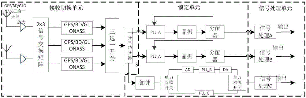
[0015] refer to figure 1 . In a preferred embodiment described below, a high-reliability frequency source device can achieve multiple high-quality standards by receiving a variety of satellite signals and built-in BM2102-06 ultra-small rubidium clock phase-locked unit and phase-locked loop Frequency signal output. The high-reliability frequency source equipment includes: a receiving switching unit, a locking unit and a signal processing unit, characterized in that: the receiving switching unit adopts two three-in-one antennas and signal amplifiers and sequentially connects 2×3 signal exchange Matrix, a 2×3 signal switching matrix switches the received satellite signals through a multi-channel receiver chip and a three-selection switch. One channel of satellite second signal is sent to a one-minute-three power divider connected in series at the output end of a three-select-one switch, and the three same-source satellite second signals separated by power are sent to two analog...


PUM


Abstract

The invention discloses a high-reliability frequency source device, and aims to provide a frequency source device with high reliability, and good long-term and short-term stability. The equipment is implemented through the following technical scheme: two three-in-one antennas and signal amplifiers are adopted by a receiving switching unit and are connected in series to form a 2*3 signal switching matrix; the 2*3 signal switching matrix switches received satellite signals via multichannel receiver chips and a one-out-three switch; the one-out-three switch receives three paths of satellite second signals which can be of a same source or different sources; one path of the satellite second signals selected is fed into a one-to-three power divider; three paths of same-source satellite second signals obtained by power dividing are respectively transmitted to a locking unit so that the input same-source satellite second signals are locked and are respectively output to a signal processing unit A and a signal processing unit B; and the other path of satellite second signals passing through the one-to-three power divider is used for carrying out frequency correction disciplining on a rubidium clock; standard frequency signals are transmitted to a signal processing unit C via a rubidium clock phase locking unit; and thus, three standard frequency signals of the same source are formed and output.

Description

technical field [0001] The invention relates to a frequency source, and more specifically, the invention relates to a high-performance time-system equipment which receives satellite signals and has a built-in phase-locked loop. Background technique [0002] The frequency standard source is to generate a standard frequency signal, and its output signal is used as the signal source of the time code generator and provided as a standard frequency signal to Doppler speed measurement and other measurement and control equipment. Commonly used frequency standard sources include quartz crystal oscillators, rubidium atomic frequency standards, cesium atomic frequency standards and hydrogen atomic frequency standards. Traditional frequency standard equipment uses atomic clocks to generate various standard frequency signals. The principle of atomic clocks is the same as that of other clocks, which use fixed-period oscillations or swings to maintain the accuracy of time measurement. The...

Claims


Application Information

Patent Timeline
Patent Type & Authority Applications(China)
IPC IPC(8): H03L7/26
CPCH03L7/26
Inventor 赵亚妮尹美良谭开洪
Owner 10TH RES INST OF CETC
Why Eureka
Try Eureka