Method for preventing welding jam of air film cooling hole

A film cooling and repair welding technology, applied in the field of welding processing, can solve problems such as hindering the smooth progress of repair work, inability to protect the film cooling holes, and blocking the film cooling holes.

Inactive Publication Date: 2016-12-21
AECC AVIATION POWER CO LTD
View PDF8 Cites 5 Cited by
  • Summary
  • Abstract
  • Description
  • Claims
  • Application Information

AI Technical Summary

Problems solved by technology

[0003] However, when the parts have cracks, ablation and other damages that need to be repaired, the film cooling holes on the parts are often blocked due to repair welding repairs of cracks and ablation, which hinders the smooth progress of the repair work.
[0004] Because the temperature of the welding part is as high as 2000°C during repair, if the film cooling hole is filled with conventional materials, the melting point of the material filled in the film cooling hole is often lower than the melting point of the base material to be welded, resulting in the failure to reach the welding point. When the base metal melts, the protective material will melt first, and the film cooling holes cannot be protected at all. This makes the film cooling holes often blocked due to the lack of effective protection methods for the film cooling holes during welding repair.

Method used


Image

  • Method for preventing welding jam of air film cooling hole

Examples


Embodiment

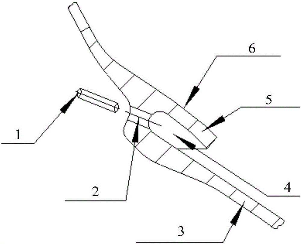
[0027] Such as figure 1 As shown, the annular flame tube of a certain type of aero-engine has a double-walled structure with film grooves, and a row of φ1 film cooling holes 2 is arranged in the middle of each film groove 4 . Because there are cracks or ablation parts 6 in the cylinder wall, it is necessary to repair the cracks or ablation parts 6 on the annular cylinder wall by manual argon arc welding when returning to the factory for overhaul. When the crack or ablation site 6 extends to the film cooling hole 2 or is close to the film cooling hole 2 , directly repairing the crack or ablation site 6 will easily cause the film cooling hole 2 to be blocked. For this reason, a φ0.9 graphite core 1 (automatic pencil core) can be inserted in the film cooling hole 2 before welding, and in order to prevent the graphite core 1 from slipping, heat-resistant adhesive tape can be used to fix both ends of the graphite core.


PUM

PropertyMeasurementUnit
diameteraaaaaaaaaa
melting pointaaaaaaaaaa

Abstract

The invention discloses a method for preventing welding jam of an air film cooling hole. The method comprises the steps that 1), a graphite core is inserted into the air film cooling hole in a part needing repair welding; 2), repair welding is conducted on cracks or ablation portions of the part; and 3), after repair welding is completed, the graphite core in the air film cooling hole is mashed and taken out. According to the method for preventing welding jam of the air film cooling hole, the graphite core is selected as a protection material, and graphite has the beneficial effects of being high in melting point, high in temperature resistance, small in thermal expansion coefficient and soft but large in brittleness; in addition, the graphite has good lubricity; when the graphite core is used for protecting the air film cooling hole, molten metal on the welding portion cannot damage the shape and the size of the air film cooling hole because of the high temperature resistance and stability of the graphite; the situation that the graphite core expands and cannot be taken out due to high temperature generated by arc burn during welding is avoided; meanwhile, the graphite has soft and lubricating characteristics, and it can be guaranteed that the post-weld graphite is not likely to be stuck in the air film cooling hole; and even if the stuck phenomenon exists, the graphite core can be mashed into powder and taken out with a tool because of the large brittleness of the graphite core.

Description

【Technical field】 [0001] The invention belongs to the field of welding processing, and relates to a method for preventing welding blockage of air film cooling holes. 【Background technique】 [0002] Film cooling holes are often designed on mechanical parts, especially on the compressors, combustion chambers and turbine blades of aero-engines and gas turbines. In order to reduce the erosion of high-temperature and high-pressure gas on parts, film cooling technology is usually used to design on parts There are one row or several rows of densely distributed φ0.5-φ2.0 film cooling holes. The cooling air passing through these film cooling holes forms a continuous and stable cooling air film, which connects the high-temperature and high-pressure gas to the wall surface of the part. Separated, so as to achieve the purpose of reducing the wall temperature of the parts. As an advanced structural design technology, film cooling is widely used in compressors, combustors and especially ...

Claims


Application Information

Patent Timeline
Patent Type & Authority Applications(China)
IPC IPC(8): B23P6/04
CPCB23P6/04
Inventor 王伟涛苏瑾钟堂韩花妮石三毛颉文峰
Owner AECC AVIATION POWER CO LTD
Why Eureka
Try Eureka