
Secondary reheating boiler type with three gas flues arranged at tail part
A technology of double reheating and boiler type, applied in steam boilers, steam superheating, lighting and heating equipment, etc., can solve the problems of boiler efficiency reduction, achieve the effects of reducing coal consumption, improving boiler efficiency, and reducing exhaust gas temperature
- Summary
- Abstract
- Description
- Claims
- Application Information
AI Technical Summary
Problems solved by technology
Method used
Image

Examples
Embodiment 1
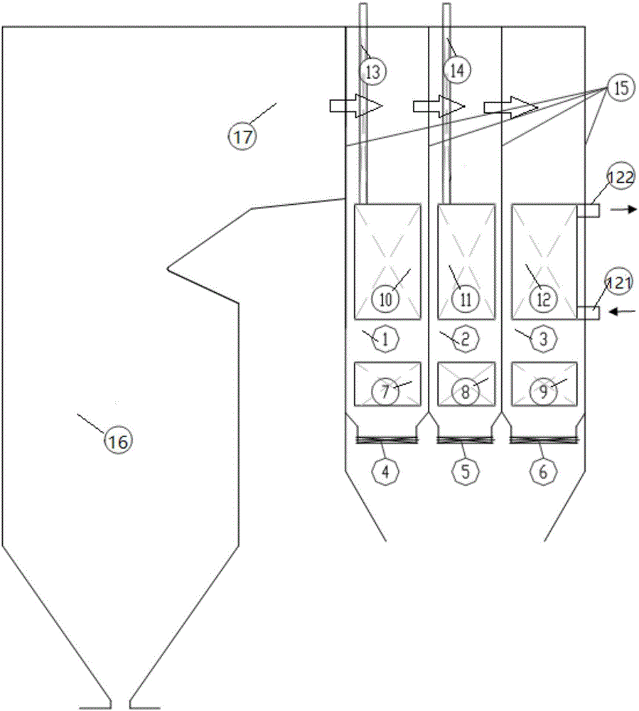
[0022] refer to figure 1 As shown in the figure, the large hollow arrow in the figure is the flow direction of the flue gas, and the small solid arrow is the flow direction of the hot secondary air. A type of secondary reheat boiler with three flues at the tail arranged, including a flue at the end, the flue at the end is divided into three flues in parallel by a cladding wall 15, namely flue 1 at the front of the tail, flue 2 in the middle of the tail, The rear flue 3 at the tail and the front flue 1 at the tail are sequentially provided with the vertical section 13 of the primary low temperature reheater, the horizontal section 10 of the primary low temperature reheater, the economizer (front) 7 and the flue gas adjusting baffle ( Front) 4, the flue 2 in the tail is sequentially provided with the vertical section 14 of the secondary low temperature reheater, the horizontal section 11 of the secondary low temperature reheater, the economizer (middle) 8 and the flue gas regula...
Embodiment 2
[0024] refer to figure 1 As shown, this embodiment is basically the same as Embodiment 1, the difference is: the low-temperature reheater of the front flue 1 at the tail is a secondary low-temperature reheater (the vertical section 13 of the secondary low-temperature reheater in turn along the flue gas direction) , the horizontal section 10 of the secondary low temperature reheater, the low temperature reheater of the flue 2 in the tail is the primary low temperature reheater (the vertical section 14 of the primary low temperature reheater and the horizontal section of the primary low temperature reheater along the flue gas direction are in turn paragraph 11).
Embodiment 3
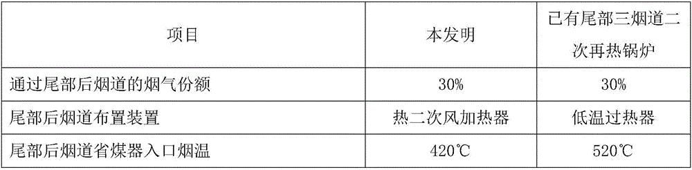
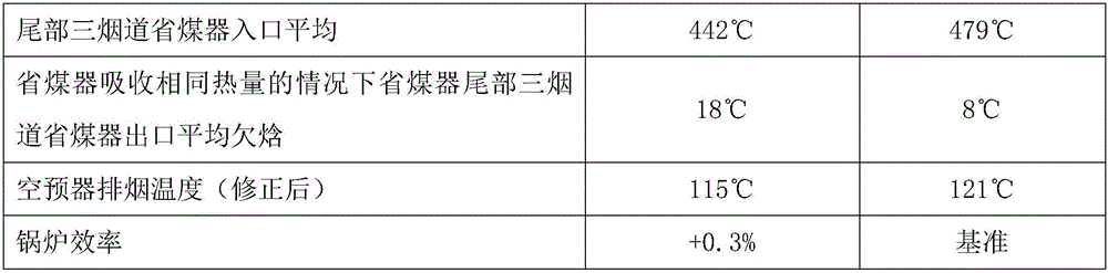
[0026] Taking the 630°C secondary reheat parameter project as an example, 30% of the flue gas in the BMCR condition passes through the rear flue (3), and this part of the flue gas heats the hot secondary air at the outlet of the air preheater. The temperature of this part of the flue gas is reduced from 735°C to 420°C, and the hot secondary air is heated from 360°C to 478°C.
[0027]
[0028]
[0029] It can be seen from the above table that, compared with the existing triple-flue secondary reheat boiler at the tail, the economizer outlet of the present invention improves the enthalpy at the exit and the boiler efficiency, which is beneficial to the safe and efficient operation of the boiler.
PUM
 Abstract
Description
Claims
Application Information