A Heterodyne 2/3D Grating Displacement Coarse/Fine Measuring System

A three-dimensional grating and fine measurement technology, applied in the direction of measuring devices, optical devices, instruments, etc., can solve the problems of unrealizable, low resolution, waste of system resources, etc.

Active Publication Date: 2018-10-12
HARBIN INST OF TECH
View PDF8 Cites 0 Cited by
  • Summary
  • Abstract
  • Description
  • Claims
  • Application Information

AI Technical Summary

Problems solved by technology

[0005] However, in all current research results on grating displacement measurement devices, the measurement resolution in the measurement process is a fixed value, that is, the same measurement resolution is used in both large-range displacement measurement and small-range displacement measurement. Realize the conversion of large-range displacement measurement using low-resolution rough measurement and small-range displacement measurement using high-resolution fine measurement, which will cause a waste of system resources
Moreover, since the measurement speed will limit the resolution of the system, that is, the higher the measurement speed, the lower the resolution of the system. Therefore, when high-resolution measurement is not necessary, the grating displacement measurement that cannot perform coarse / fine measurement conversion is still used. The device will limit the measurement speed of the system, thereby affecting the running speed of the motion device to be tested

Method used


Image

  • A Heterodyne 2/3D Grating Displacement Coarse/Fine Measuring System
  • A Heterodyne 2/3D Grating Displacement Coarse/Fine Measuring System

Examples


Embodiment Construction

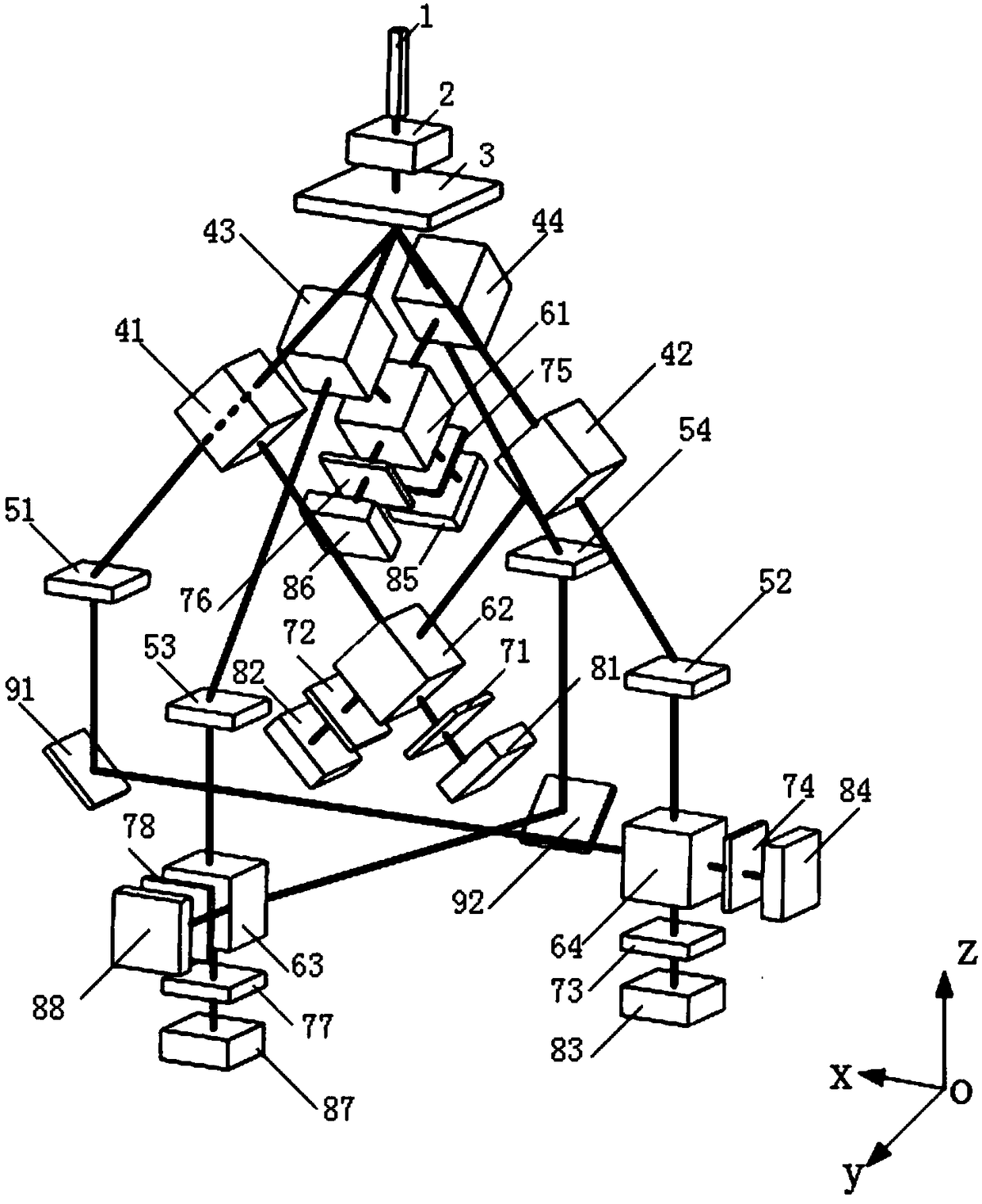
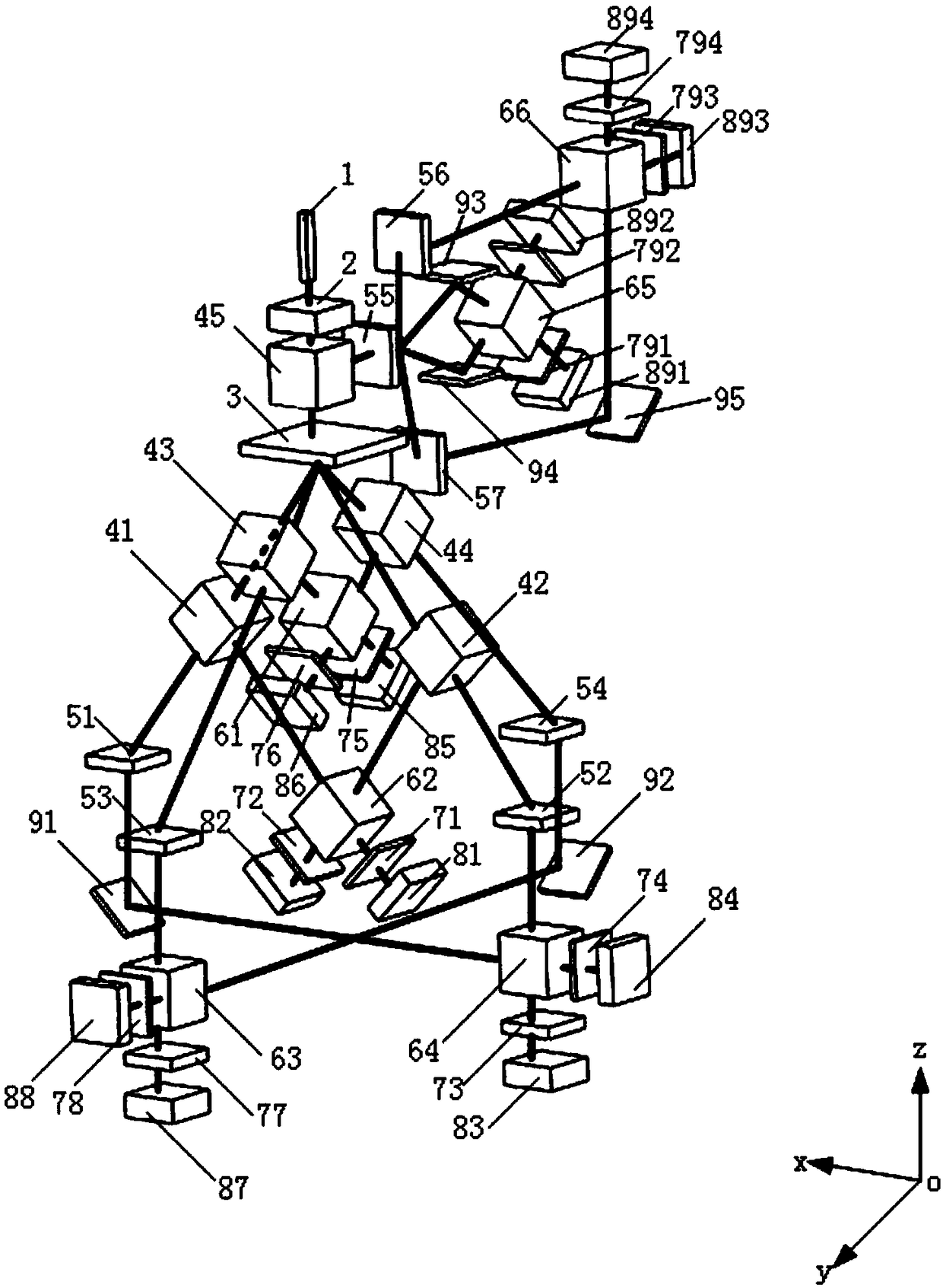
[0020] figure 1 Shown is the two-dimensional grating displacement coarse / fine measuring part of the present invention, which includes a single-frequency laser light source 1; an electro-optical modulator 2; a two-dimensional transmission measuring grating 3; a first beam splitting prism 41; a second beam splitting prism 42; Three dichroic prism 43; fourth dichroic prism 44; first one-dimensional transmission measurement grating 51; second one-dimensional transmission measurement grating 52; third one-dimensional transmission measurement grating 53; fourth one-dimensional transmission measurement grating 54 ; the first polarizing beam splitting prism 61; the second polarizing beam splitting prism 62; the third polarizing beam splitting prism 63; the fourth polarizing beam splitting prism 64; the first polarizing plate 71; the second polarizing plate 72; the third polarizing plate 73; the fourth polarizing plate plate 74; fifth polarizer 75; sixth polarizer 76; seventh polarizer...


PUM


Abstract

The invention relates to a heterodyne type two / three-dimensional grating displacement coarse / fine measuring system. The system comprises a single-frequency laser light source, an electro-optic modulator, five beam splitter prisms, a two-dimensional transmission type measuring grating, seven one-dimensional transmission type measuring gratings, six polarization beam splitter prisms, twelve polaroids, twelve photoelectric detection and signal processing components and five plane mirrors; laser emitted by the single-frequency laser light source is linearly polarized single-frequency laser, the polarization direction of the laser forming a 45-degree angle with an x axis; the laser is modulated through the electro-optic modulator of which the fast axis direction is parallel to the x axis, so that heterodyne laser can be outputted; the heterodyne laser is composed of an s wave component of which the polarization direction is along a y axis and a p wave component of which the polarization direction is along the x axis; and the s wave component and the p wave component have a phase difference which changes with the change of modulated voltage loaded by the electro-optic modulator. With the heterodyne type two / three-dimensional grating displacement coarse / fine measuring system of the invention adopted, errors caused by factors, such as ambient temperature and humidity change, can be avoided; and the coarse / fine conversion of displacement measurement resolution in two / three-dimensional directions can be realized, and different measurement needs can be fully satisfied.

Description

Technical field: [0001] The invention relates to a grating displacement measurement system, in particular to a heterodyne type two / three-dimensional grating displacement coarse / fine measurement system. Background technique: [0002] Grating displacement measurement technology first originated in the 19th century and has developed rapidly since the 1950s. At present, the grating displacement measurement system has become a typical high-precision displacement measurement method, and is widely used in many opto-mechanical devices. Due to the advantages of high resolution, high precision, low cost, and low environmental sensitivity, the grating displacement measurement system has not only been widely used in industry and scientific research, but has also been studied by domestic and foreign scholars and scientific research institutions. [0003] In the fields of semiconductor technology, nanotechnology and biotechnology, precision displacement measurement systems and position p...

Claims


Application Information

Patent Timeline
Patent Type & Authority Patents(China)
IPC IPC(8): G01B11/02
CPCG01B11/02
Inventor 林杰陈航关健金鹏谭久彬
Owner HARBIN INST OF TECH
Why Eureka
Try Eureka