Holographic reflective array compact range

A reflective array and compact field technology, applied in antenna radiation patterns, radio wave measurement systems, instruments, etc., can solve difficult manufacturing costs and other problems, and achieve the effect of simple manufacture, light structure, and easy installation

Active Publication Date: 2016-12-21
BEIHANG UNIV
View PDF3 Cites 16 Cited by
  • Summary
  • Abstract
  • Description
  • Claims
  • Application Information

AI Technical Summary

Problems solved by technology

Traditional reflector antennas are limited by machining accuracy, so it is difficult to apply to the submillimeter wave band or the manufacturing cost is too high

Method used


Image

  • Holographic reflective array compact range
  • Holographic reflective array compact range
  • Holographic reflective array compact range

Examples


Embodiment Construction

[0022] The present invention will be described in detail below in conjunction with the accompanying drawings and specific embodiments.

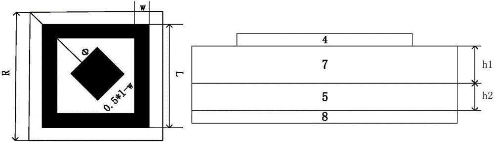
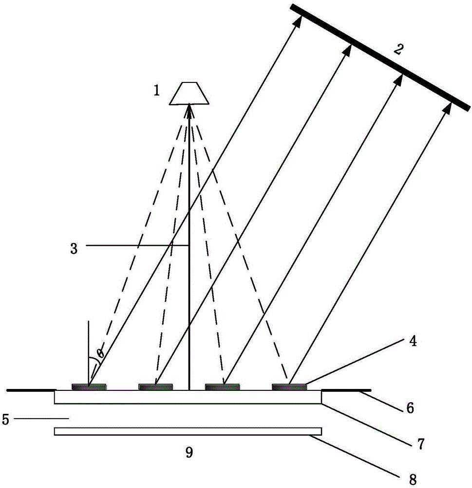
[0023] Such as image 3 As shown, the reflectarray antenna 9 is composed of a reflectarray unit 4, a dielectric substrate 7, an air layer 5, and a ground plate 8. Reflector units 4 of different sizes have different abilities to adjust the phase of electromagnetic waves. The manufacture of the reflectarray antenna 9 It can be manufactured using a PCB process.

[0024] The function of the reflectarray antenna 9 is to correct the spherical wave emitted by the feed source into a plane wave at a short distance.

[0025] The feed source 1 feeds forward and vertically irradiates the reflectarray antenna 9 to ensure that the aperture is uniformly irradiated, and the spherical wave approximately vertically irradiates all the reflectarray units 4 .

[0026] The narrow field focal length 3 of the holographic reflectarray is set to 1.5 times the side l...


PUM


Abstract

The invention relates to a holographic reflective array compact range. The holographic reflective array compact range is composed of a feed source, a reflective array antenna and edge teeth, wherein the feed source is fed forward and is vertically irradiated on the reflective array antenna, the reflective array antenna corrects spherical waves emitted by the feed source into plane waves at a close distance, and through caliber layout and inhibition of edge diffraction via the edge teeth, a specific plane wave dead zone is generated so that the far-field condition demand of an antenna pattern or a target RCS test is satisfied. According to the invention, the processing precision of the reflective array antenna is lower than a conventional reflection plane by one order of magnitude, a printing structure is employed, the structure is portable, the manufacturing is simple, the installation is convenient, the manufacturing cost can be decreased, and the holographic reflective array compact range is suitable for low-cost construction of a radiation or scattering test system of a millimeter wave/submillimeter wave band.

Description

technical field [0001] The present invention relates to a compact field technology, in particular to a novel holographic reflective array compact field, which is mainly used in millimeter wave / submillimeter wave testing and can meet the far-field condition requirements of antenna pattern or target RCS testing. Background technique [0002] With the rapid development of millimeter wave\submillimeter wave technology, the demand for millimeter wave\submillimeter wave antenna testing is becoming increasingly urgent. Traditional near-field and outdoor far-field have insurmountable defects in millimeter wave testing. The compact field technology plays an irreplaceable important role in millimeter wave antenna testing technology. Traditional reflector antennas are limited by machining accuracy, so it is difficult to apply to the submillimeter wave band or the manufacturing cost is too high. Contents of the invention [0003] The technology of the present invention solves the pr...

Claims


Application Information

Patent Timeline
Patent Type & Authority Applications(China)
IPC IPC(8): G01R29/10G01S7/41
CPCG01R29/10G01S7/41
Inventor 李志平赵健武建华王正鹏
Owner BEIHANG UNIV
Why Eureka
Try Eureka