Monitoring vidicon cooling method and structure based on thermal pressure effect

A monitoring camera and heat dissipation structure technology, applied in image communication, color TV parts, TV system parts, etc., can solve problems such as lifespan reduction, high temperature, and affecting the quality of captured images, and achieve enhanced convective heat transfer , increase the heat dissipation effect, avoid the effect of insufficient heat dissipation

Active Publication Date: 2016-12-21
ZHEJIANG UNIV
View PDF5 Cites 10 Cited by
  • Summary
  • Abstract
  • Description
  • Claims
  • Application Information

AI Technical Summary

Problems solved by technology

In addition, since the cavity containing electronic devices in the surveillance camera is often completely sealed, the air flow between the interior and the outside cannot be exchanged very well, resulting in a similar greenhouse effect. Forced convection fan, but the effect of the fan is not significant because the heat exchange is still mainly limited by the heat conduction of the inner casing of the surveillance camera and the external convection heat dissipation
Under the influence of many aspects, the temperature of the internal components of the surveillance camera is too high, which affects the quality of the captured image
Under the harsh conditions of direct sunlight in summer, the temperature inside the camera can be higher than the ambient temperature by more than 15°C. Excessively high temperature may cause camera distortion and shorten the lifespan

Method used


Image

  • Monitoring vidicon cooling method and structure based on thermal pressure effect
  • Monitoring vidicon cooling method and structure based on thermal pressure effect

Examples


Embodiment Construction

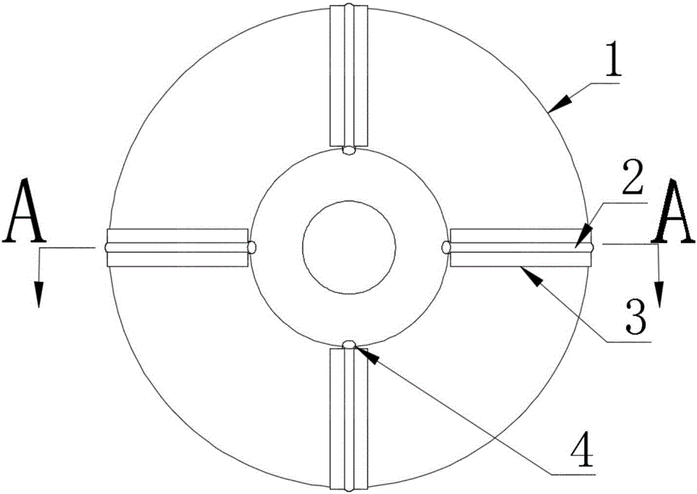
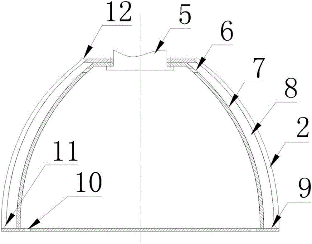
[0018] Such as figure 1 , 2 As shown, a monitoring camera heat dissipation structure based on the thermal pressure effect includes a heat shielding shell 1, a finned tube 2, a hoisting structure 5, an inner shell 7, and a bottom cover 9; between the heat shielding shell 1 and the inner shell 7 There is an air interlayer 8, and the bottom is sealed by a bottom cover 9,

[0019] The finned tube 2 is installed on the surface of the heat-shielding shell 1. One end of the finned tube 2 is connected to the environment, and the other end is connected to the air interlayer 8. The inner shell 7 is provided with a number of inner shell vent holes 6, and the inner shell vent holes 6 make the air interlayer 8 communicates with the gas space inside the inner shell, and the bottom cover 9 is provided with several bottom cover air intake holes 10, the bottom cover air intake holes 10 make the gas space inside the inner shell communicate with the environment, and the hoisting structure 5 is ...


PUM


Abstract

The invention discloses a monitoring vidicon cooling method and structure based on a thermal pressure effect. The structure comprises a heat insulation shell, an inner shell, a finned tube, a lifting structure and a bottom cover. According to the monitoring vidicon cooling method and structure disclosed by the invention, gas of the finned tube is heated by solar radiation to form a thermal pressure suction effect, so that gas in an air interlayer of the shell and the inner shell in the monitoring vidicon flows integrally; therefore, the convection heat exchange effect of the wall surface of the inner shell is enhanced; the cooling effect is improved; simultaneously, due to gas flowing, the temperature of electronic devices in the interlayer and the inner shell is kept constant; and too-high temperature rising due to poor cooling in a closed state can be avoided.

Description

technical field [0001] The invention relates to a monitoring camera heat dissipation method and structure based on thermal pressure effect, and belongs to the technical field of security monitoring equipment. Background technique [0002] At this stage, the coverage of cameras used in the field of security monitoring has become higher and higher, and many of them are located in various open-air environments such as traffic intersections and tourist attractions. atmosphere. [0003] On the one hand, the use of electronic devices in the camera will inevitably generate heat, and the requirements of surveillance cameras require the camera to run for a long time, making it easier to accumulate heat. On the other hand, in an outdoor environment exposed to direct sunlight, solar radiation causes the temperature of the surveillance camera housing to rise, which in turn conducts heat to internal components. In addition, since the cavity containing electronic devices in the surveill...

Claims


Application Information

Patent Timeline
Patent Type & Authority Applications(China)
IPC IPC(8): H04N5/225H05K7/20
CPCH05K7/20145H04N23/50
Inventor 程攻孙志坚胡亚才黄浩俞自涛陈天宇
Owner ZHEJIANG UNIV
Why Eureka
Try Eureka