
Method for treating waste oil-based drilling cuttings produced by oil field drilling operation

A technology for oil field drilling and oil-based drilling cuttings, which is applied in the field of treatment of waste oil-based drilling cuttings produced by oilfield drilling operations, can solve the problems of oilfields failing to meet environmental protection requirements and meet the standard treatment technology, etc., and achieve harmless treatment and eliminate pollution. Effect

Inactive Publication Date: 2017-01-04
PETROCHINA CO LTD +2
View PDF4 Cites 10 Cited by
  • Summary
  • Abstract
  • Description
  • Claims
  • Application Information

AI Technical Summary

Problems solved by technology

[0004] The present invention aims to overcome the problem in the background technology that the existing oil fields cannot meet the requirements of environmental protection and realize the standard treatment technology for waste oil-based cuttings produced by oil field drilling operations, and provides a treatment method for waste oil-based cuttings produced by oil field drilling operations

Method used


Image

  • Method for treating waste oil-based drilling cuttings produced by oil field drilling operation

Examples


Embodiment 1

[0028] Harmless treatment of waste oil-based drilling cuttings produced by about 1,000 tons of drilling operations in Daqing Oilfield, and a set of 24t / d oxygen barrier indirect heating rotary furnace pyrolysis process, with a treatment period of about 1.5 months. Before feeding materials, start the nitrogen making system to fill nitrogen into the rotary pyrolysis furnace to drive away the air to ensure an oxygen-isolated environment in the pyrolysis furnace; at the same time, according to the temperature control system settings, light the burner in the combustion chamber to reduce the temperature Control the temperature between 150°C and 180°C, control the temperature in the analysis chamber between 300°C and 400°C, ensure that the rotation speed of the rotary pyrolysis furnace is 1r / min, and start feeding. The material is continuously transported to the sealed chamber of the rotary pyrolysis furnace through a fully enclosed pipeline at a rate of 1t / h by a mud pump. The resid...

Embodiment 2

[0033] Daqing Oilfield conducts harmless treatment of about 300t of waste oil-based drilling cuttings generated from drilling operations, and provides a set of 12t / d oxygen barrier indirect heating rotary furnace pyrolysis process, with a treatment period of one month. Before feeding materials, start the nitrogen making system to fill nitrogen into the rotary pyrolysis furnace to drive away the air to ensure an oxygen-isolated environment in the pyrolysis furnace; at the same time, according to the temperature control system settings, light the burner in the combustion chamber to reduce the temperature Control the temperature between 150°C and 180°C, control the temperature in the analysis chamber between 300°C and 400°C, ensure that the rotation speed of the rotary pyrolysis furnace is 1r / min, and start feeding. The material is continuously transported to the sealed chamber of the rotary pyrolysis furnace through a mud pump at a rate of 0.5t / h through a fully enclosed pipeline...


PUM


Abstract

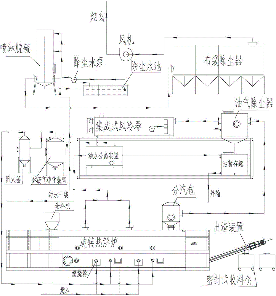
The invention relates to a method for treating waste oil-based drilling cuttings produced by oil field drilling operation, mainly aiming at solving the technical problems that the existing oil fields do not have a technology which is in accordance with the requirements of environmental protection and can realize standard treatment on the waste oil-based drilling cuttings produced by the oil field drilling operation. The method comprises the following steps: (1) feeding material into a system in a closed way; (2) carrying out rotary pyrolysis treatment on the material in a way of oxygen insulation; (3) treating and recycling pyrolysis steam; (4) treating and recycling non-condensable gas; (5) treating and discharging flue gas; (6) automatically discharging residue out of the system at high temperature. The method for treating the waste oil-based drilling cuttings produced by the oil field drilling operation can not only realize harmless treatment on the waste oil-based drilling cuttings produced by the oil field drilling operation, but also can recycle a great deal of fuel oil and flammable gas from the waste oil-based drilling cuttings, thus being beneficial to the production of an oil field and the completion of productivity indexes.

Description

technical field [0001] The invention relates to a treatment method for waste oil-based drilling cuttings in the technical field of oilfield resources and environment, in particular to a treatment method for waste oil-based drilling cuttings produced in oilfield drilling operations. Background technique [0002] During oil field drilling operations, drilling fluids are required to clean the bottom of the well, carry cuttings, cool and lubricate the drill bit and drill string, stabilize and protect the well wall, and protect the oil and gas layers. Drilling fluid is a circulating fluid used in the drilling process. It is a mixture of liquid, solid and chemical treatment agents. It is mainly divided into two types: water-based and oil-based mud. Oil-based mud is widely used due to its advantages of high temperature resistance, salt and calcium corrosion resistance, good lubricity, and damage to oil and gas layers. However, after the application of drilling fluid, especially oi...

Claims


Application Information

Patent Timeline
IPC IPC(8): C10G1/00
CPCC10G1/00C10G2300/1003
Inventor 冯英明韩凤臣李卓夏福军
Owner PETROCHINA CO LTD
Learn More