
Ion collision accelerated electric thruster device

An electric thruster, ion collision technology, applied in thrust reverser, using plasma, machine/engine and other directions, can solve the problems of annular channel wall corrosion, ion optical system corrosion, low specific impulse, etc. The effect of reducing sputter erosion, high specific impulse performance

Inactive Publication Date: 2019-06-25
DALIAN UNIV OF TECH
View PDF2 Cites 0 Cited by
  • Summary
  • Abstract
  • Description
  • Claims
  • Application Information

AI Technical Summary

Problems solved by technology

Although the Hall thruster has a high thrust density, its specific impulse is relatively low. The experimental research on the Hall thruster shows that the anode is corroded after hundreds of hours of working with nitrogen or nitrogen / oxygen mixed gas. Quite serious, under the condition of oxygen discharge, the corrosion of the wall surface of the annular channel is very serious, which cannot meet the requirements of low-orbit air-breathing electric propulsion applications
[0008] For electrostatic electric thrusters, whether it is a microwave ion thruster or a radio frequency ion thruster, the structure of the thruster contains an ion optical system and is relatively complicated. As a low-orbit spacecraft air-breathing electric propulsion, the reliability of the overall system is greatly reduced , and the ion optical system that accelerates ion ejection has obvious corrosion when using atmospheric components as the propellant, so it cannot meet the working environment and requirements of the air-breathing electric propulsion system

Method used


Image

  • Ion collision accelerated electric thruster device
  • Ion collision accelerated electric thruster device
  • Ion collision accelerated electric thruster device

Examples


Embodiment Construction

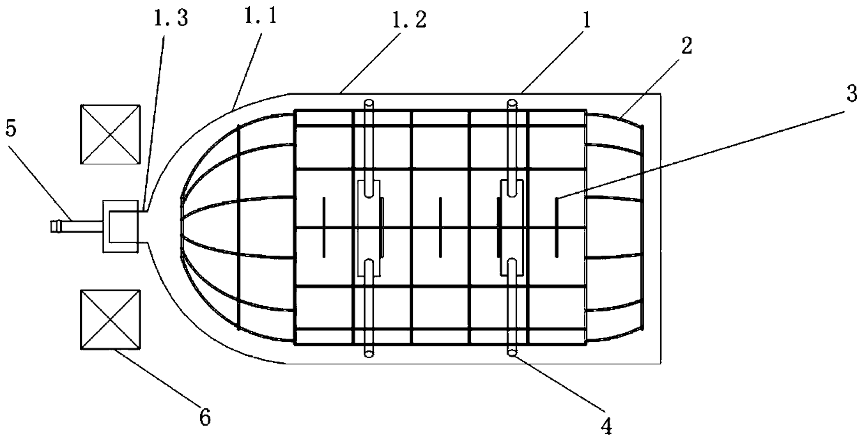
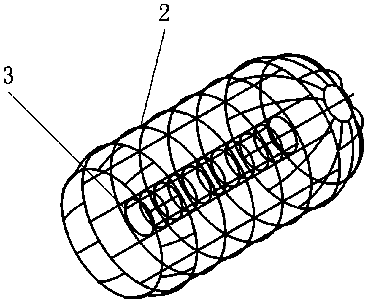
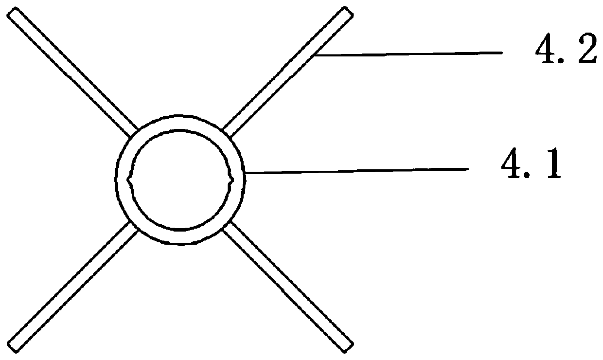
[0038] The specific embodiment of the present invention is shown in the accompanying drawings. The ion collision accelerated electric thruster device includes: a quartz tube 1, an anode grid 2, a cathode grid 3, a cathode support frame 4, an electrical inlet 5 and a permanent magnet ring 6;

[0039] The quartz tube 1 is a cylindrical structure; it includes a tube part 1.2, a hemispherical part 1.1, and a guide hole part 1.3; the hemispherical part 1.1 is mounted on one end of the tube part 1.2; The barrel remains coaxial;

[0040] The anode grid 2 is attached to the inner wall of the quartz tube 1;

[0041] The cathode grid 3 is installed inside the quartz tube 1 through the cathode support frame 4; the cathode grid 3, the anode grid 2 and the quartz tube 1 are coaxially arranged;

[0042] The electrical inlet 5 is fixedly connected to the guide hole 1.3;

[0043] The permanent magnet ring 6 is installed outside the guide hole portion 1.3 and coaxially assembled with the ano...


PUM


Abstract

The invention discloses an ion collision acceleration type electric thruster device and relates to the field of aspiration type electric propulsion of low-orbit spacecraft. The ion collision acceleration type electric thruster device comprises a quartz tube, an anode grid, a cathode grid, a cathode support rack, an electric inlet and a permanent magnetic ring, wherein the cylindrical quartz tube comprises a tube cylinder part, a semi-sphere part and a guide hole part, the semi-sphere part is mounted at one end of the tube cylinder part, the guide hole part is mounted at the top of the semi-sphere part and is coaxial with the tube cylinder part, the anode grid attaches to the inner wall of the quartz tube, the cathode grid is mounted in the quartz tube through the cathode support rack, the cathode grid, the anode grid and the quartz tube are coaxial, the electric inlet is fixedly connected to the guide hole part, and the permanent magnetic ring is mounted outside the guide hole part and coaxially assembled with the anode grid and the cathode grid. The novel ion collision acceleration type electric thruster device is novel in structure, simple to produce and machine, stable in performance, safe, reliable, widely applicable, economic and practical.

Description

technical field [0001] The ion collision accelerated electric thruster device of the invention relates to the field of air-breathing electric propulsion of low-orbit spacecraft. Background technique [0002] In recent years, with the rapid development of international aerospace technology, low-orbit satellite mobile communication systems, such as Iridium (Iridium) system, Aries (Arics) system, low-orbit satellite (Leo-Set) system, satellite communication network (Teledesic) system , low-orbit Earth observation satellites, low-orbit scientific platforms, low-orbit military reconnaissance satellites and spy satellites, and space stations and space laboratories and other low-orbit vehicles have gradually become important members of the spacecraft family. [0003] In order to improve the life of the satellite, save the cost of launching the satellite, and reduce the cost, the high-specification electric propulsion technology that can reduce the consumption of propellant has been...

Claims


Application Information

Patent Timeline
Patent Type & Authority Patents(China)
IPC IPC(8): F03H1/00
CPCF03H1/0081
Inventor 夏广庆周念东吴秋云王鹏邹存祚韩亚杰陈留伟
Owner DALIAN UNIV OF TECH
Learn More