Natural circulation split tube-and-shell type waste heat boiler capable of optimizing flow field arrangement

A natural circulation and waste heat boiler technology, applied in water tube steam boilers, steam boilers, steam boiler accessories, etc., can solve the problems of shortening the service life of heat exchange tubes, cracking and leakage of tube plates, and large heat flux density, etc., to reduce fluctuations , solve the effect of flow stagnation or even backflow, and avoid obstruction

Active Publication Date: 2017-01-04
XI AN JIAOTONG UNIV
View PDF6 Cites 10 Cited by
  • Summary
  • Abstract
  • Description
  • Claims
  • Application Information

AI Technical Summary

Problems solved by technology

Between the drum heat exchange tube bundles, flow is closely related to heat exchange, and the turbulent flow of vapor-liquid two-phase fluid will inevitably cause heat transfer deterioration in local areas, greatly shortening the service life of heat exchange tubes
[0006] In addition, the welding between the front and rear tube sheets and the shell and between the tube sheets and the heat exchange tubes of the drum are all welded with dissimilar steels, especially at the front tube sheet where the flue gas temperature is high and the heat flux density is high, which is very easy to Safety accidents such as tube sheet cracking and leakage occur, increasing unplanned maintenance of boilers during operation

Method used


Image

  • Natural circulation split tube-and-shell type waste heat boiler capable of optimizing flow field arrangement
  • Natural circulation split tube-and-shell type waste heat boiler capable of optimizing flow field arrangement
  • Natural circulation split tube-and-shell type waste heat boiler capable of optimizing flow field arrangement

Examples


Embodiment Construction

[0041] The present invention will be described in further detail below in conjunction with the accompanying drawings.

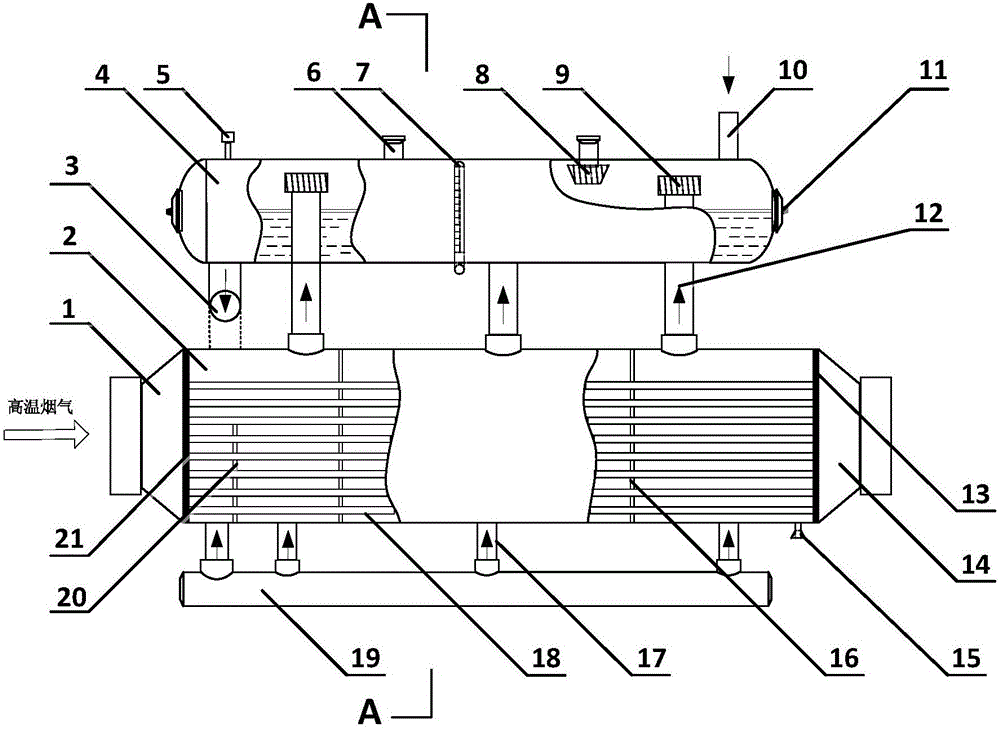
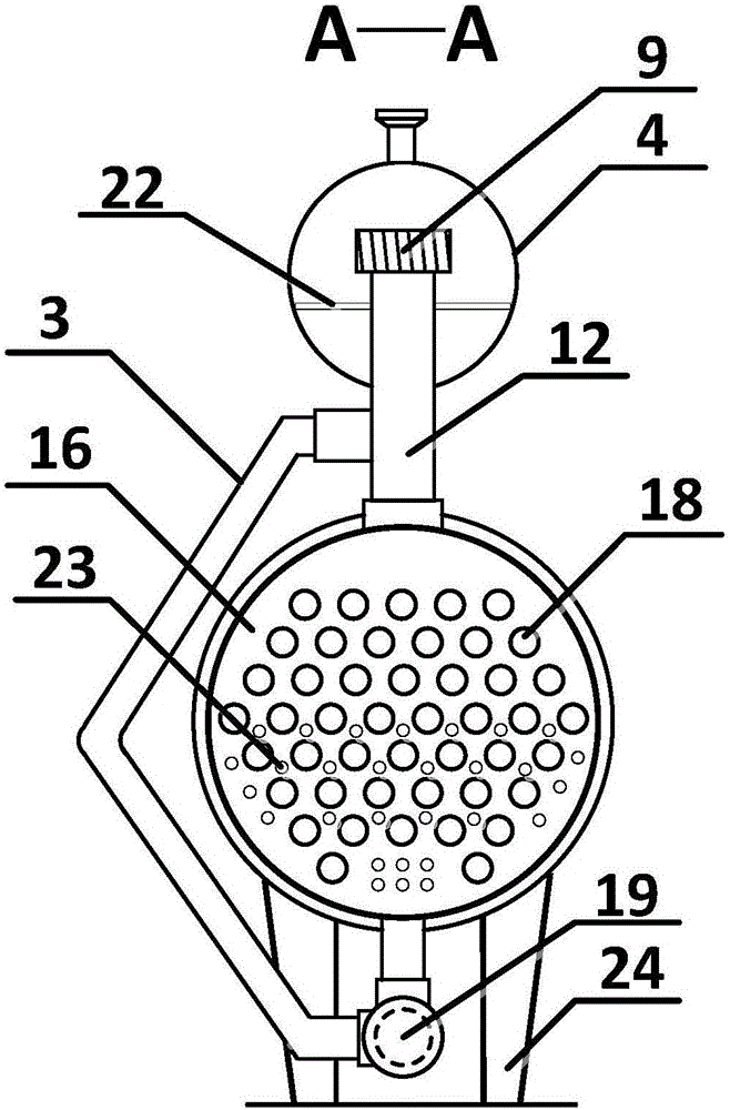
[0042] see figure 1 with figure 2, the present invention includes a drum 2 and a steam drum 4 arranged sequentially from bottom to top, and the drum 2 is installed on a boiler support 24; wherein the drum 2 includes a shell, and a vertical front tube plate 21 and a rear tube plate 21 are installed in the shell. The tube sheet 13 , the front tube sheet 21 and the rear tube sheet 13 divide the interior of the shell into a flue gas inlet 1 , a heat exchange chamber and a flue gas outlet 14 in sequence.

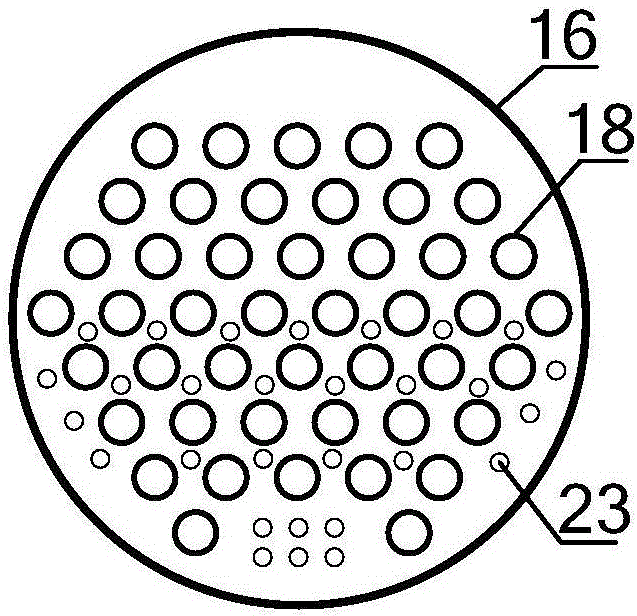
[0043] The lower side of the heat exchange chamber is connected to the water collection pipe 19 through several first water distribution pipes 17 arranged side by side; a heat exchange tube bundle is arranged in the heat exchange chamber, and the two ends of the heat exchange tube bundle are respectively expanded and welded with the front tube plate 21 and the...


PUM


Abstract

The invention relates to a natural circulation split tube-and-shell type waste heat boiler capable of optimizing flow field arrangement. The waste heat boiler comprises a boiler barrel and a steam pocket. The boiler barrel is partitioned into a flue gas inlet, a heat exchange cavity and a flue gas outlet. The heat exchange cavity is connected with a water collection pipe through a first water distribution pipe. A heat exchange pipe bundle is arranged in the heat exchange cavity. The heat exchange cavity is internally partitioned into multiple heat exchange units by arranging vertical support baffles. Each heat exchange unit is connected with the steam pocket through an ascending pipe. The upper end of each ascending pipe extends into the steam pocket and is always located above the liquid level in the steam pocket. Pipe holes used for allowing the heat exchange pipe bundle to penetrate are formed in the support baffles. Baffle holes are formed among the pipe holes in the lower portions of the support baffles. The steam pocket is provided with a steam pocket water replenishing opening and multiple steam outlets. The steam pocket is connected with the water collection pipe through a descending pipe. By means of the natural circulation split tube-and-shell type waste heat boiler, the problems that in a boiler barrel on the lower portion in a split tube-and-shell type waste heat boiler, steam-liquid two-phase flow is disorder, and in ascending pipes, steam-liquid two-phase flow stagnates and even backflow is caused can be solved.

Description

[0001] 【Technical field】 [0002] The invention relates to the field of waste heat recovery, in particular to a natural circulation split shell-and-tube waste heat boiler with optimized flow field arrangement. [0003] 【Background technique】 [0004] Waste heat resources, also known as waste heat resources, refer to energy such as heat energy discharged from energy utilization equipment or systems that may be recycled and utilized under current conditions. The waste heat boiler is an important equipment for recovering high-temperature flue gas waste heat. Its essence is a heat exchanger that uses high-temperature flue gas as a heat source to generate steam. The steam generated can be used for power generation, heating, and chemical raw materials. The traditional shell-and-tube waste heat boiler adopts a single-tube shell structure, and the steam generated by the phase change of the working fluid when heated is separated in the same space. In the petrochemical industry, when th...

Claims


Application Information

Patent Timeline
IPC IPC(8): F22B1/18F22B15/00F22B31/08F22B37/20F22B37/26
CPCF22B1/1884F22B15/00F22B31/08F22B37/205F22B37/26
Inventor 邵怀爽梁志远赵钦新魏玉伟王云刚
Owner XI AN JIAOTONG UNIV
Why Eureka
Try Eureka