Molten slag discharging devices and plasma furnace

A technology of discharge device and plasma furnace, applied in the field of ion furnace, can solve the problems of melting body scarring and clogging the slag discharge pipe, and achieve the effect of avoiding solidification

Active Publication Date: 2017-01-04
浙江民生源环保设备有限公司
View PDF5 Cites 3 Cited by
  • Summary
  • Abstract
  • Description
  • Claims
  • Application Information

AI Technical Summary

Problems solved by technology

[0005] The purpose of the present invention is to provide a slag discharge device and a plasma furnace to s

Method used


Image

  • Molten slag discharging devices and plasma furnace
  • Molten slag discharging devices and plasma furnace
  • Molten slag discharging devices and plasma furnace

Examples


Embodiment 1

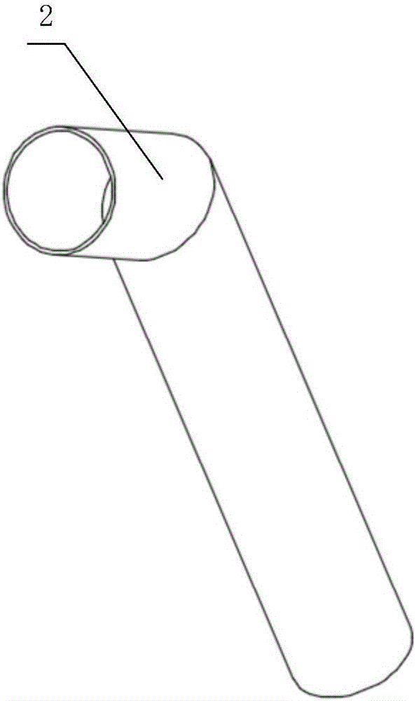
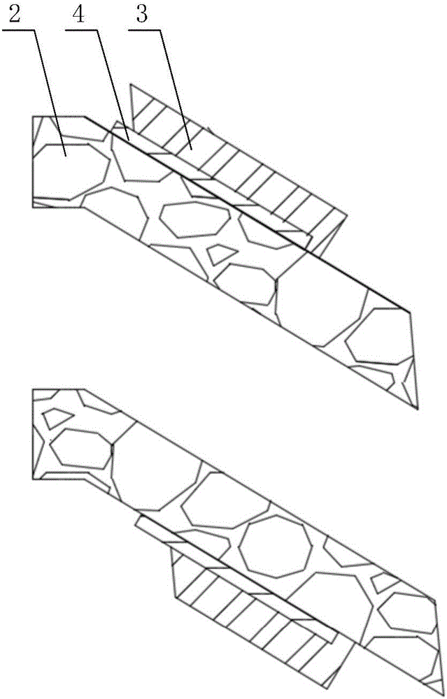
[0038] figure 1 It is a structural schematic diagram of the slag discharge device described in the embodiment of the present invention; figure 2 for figure 1 A cross-sectional view of the slag discharge device;

[0039] Such as Figure 1-2 As shown, the present invention provides a slag discharge device, which includes a slag discharge pipe 2 for discharging the molten material. The outer layer of the slag discharge pipe 2 is provided with a thermal insulation bushing 3. There is a heating element 4 between them.

[0040] The invention provides a slag discharge device, through the slag discharge pipe 2, the thermal insulation bushing 3 on the outer layer of the slag discharge pipe 2, and the heating element 4 between the slag discharge pipe 2 and the thermal insulation bushing 3, the high-temperature melt When discharged from the slag discharge pipe 2, the high-temperature melt can be kept at a high temperature by the heating of the heating element 4, thereby preventing t...

Embodiment 2

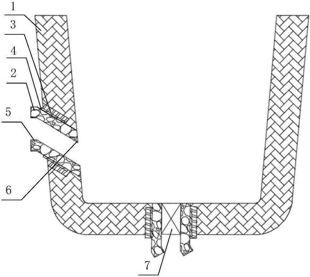
[0060] image 3 It is a structural schematic diagram of the plasma furnace described in the embodiment of the present invention.

[0061] The present invention also provides a plasma furnace, comprising a furnace body 1 and the slag discharge device described in the present invention, at least one slag discharge device is provided; the slag discharge device is arranged obliquely on the side wall of the furnace body 1, and the slag discharge device The height of the outlet bottom 5 of the slag discharge pipe of the device is higher than the height of the top 6 of the slag discharge pipe inlet.

[0062] The slag discharge pipe 2 is installed obliquely on the furnace body 1, and the height of the bottom 5 of the slag discharge pipe outlet is higher than the height of the top 6 of the slag discharge pipe inlet, which can effectively increase the residence time of solid waste in the high-temperature furnace and facilitate the melting of the melt The degree of uniformity and vitrif...


PUM


Abstract

The invention provides molten slag discharging devices and a plasma furnace. Each molten slag discharging device comprises a slag discharging pipe for discharging melt; an outer layer of the slag discharging pipe is provided with a heat preservation lining sleeve; and a heating element is arranged between the slag discharging pipe and the heat preservation lining sleeve. The plasma furnace comprises a furnace body and the molten slag discharging devices. The number of the molten slag discharging devices is at least two. One of the molten slag discharging devices is obliquely arranged on the side wall of the furnace body, and the bottom of an outlet of the slag discharging pipe of the molten slag discharging device is higher than the top of an inlet of the slag discharging pipe. The other molten slag discharging device is perpendicular to the bottom of the furnace body, and a switch is arranged in the slag discharging pipe of the molten slag discharging device.

Description

technical field [0001] The invention relates to the technical field of thermal energy and environmental engineering, in particular to a slag discharge device and a plasma furnace. Background technique [0002] With the development of industry and the improvement of people's living standards, various wastes are continuously produced. At present, wastes such as medical waste, electronic waste and footwear scraps are simply buried or incinerated when they are disposed of. Since the above-mentioned wastes are directly buried, they will pollute the soil and groundwater and take up a lot of space. During the incineration process, due to the temperature limitation, some toxic components and substances that are difficult to incinerate still exist, and the temperature is difficult to control. Toxic gases, such as dioxin, carbon monoxide, etc., and those incinerated residues and fly ash still need to be landfilled. [0003] In response to the above problems, people try to use arc pla...

Claims


Application Information

Patent Timeline
IPC IPC(8): F23G5/44F23J1/08
CPCF23G5/44F23J1/08
Inventor 楼顺来楼家豪楼国豪任其龙
Owner 浙江民生源环保设备有限公司
Why Eureka
Try Eureka