
Calorimetric pool for uniformly adding mobile phase in calorimetric apparatus

A mobile phase, calorimetric technology, applied in the field of calorimetric cells, can solve problems such as poor mixing effect

Active Publication Date: 2017-01-04
CHINA PETROLEUM & CHEM CORP +1
View PDF8 Cites 2 Cited by
  • Summary
  • Abstract
  • Description
  • Claims
  • Application Information

AI Technical Summary

Problems solved by technology

[0007] The technical problem to be solved by the present invention is the problem of poor mixing effect in the prior art, and a new calorimetric cell that uniformly adds mobile phase to the calorimetric equipment is provided

Method used


Image

  • Calorimetric pool for uniformly adding mobile phase in calorimetric apparatus
  • Calorimetric pool for uniformly adding mobile phase in calorimetric apparatus
  • Calorimetric pool for uniformly adding mobile phase in calorimetric apparatus

Examples


Embodiment 1

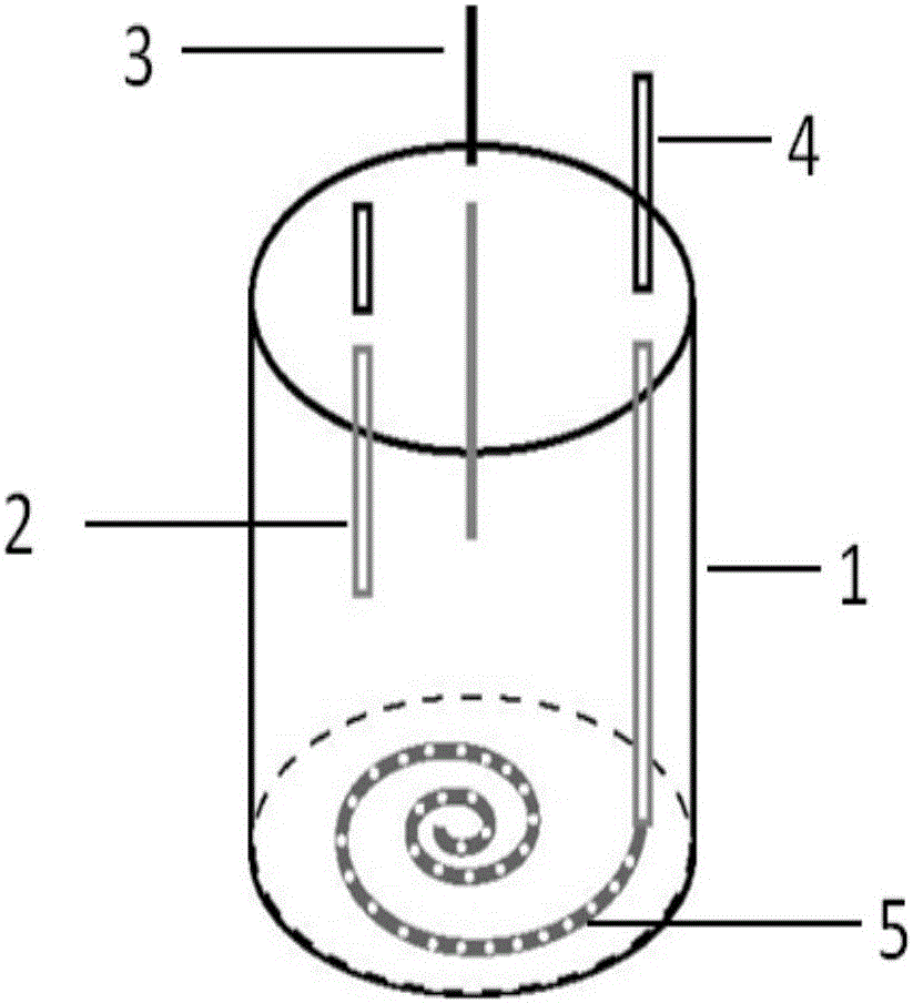
[0020] A calorimetric cell in which the mobile phase is uniformly added to the calorimetric device, such as figure 1 As shown, it includes reaction cell, reaction cell shell, temperature and pressure sensor probes, stationary phase injection port, mobile phase injection channel, porous disperser, and the top of the reaction cell is provided with a sleeve, and the temperature sensor probe is placed in the concave The pressure sensor probe is located in the gas phase space on the top of the reaction cell, the stationary phase injection port is located on the top of the reaction cell, the mobile phase injection channel is located on the top of the reaction cell, and extends into the reaction cell. One end is connected with a porous disperser, and the porous disperser is distributed at the bottom of the reaction pool in a flat manner or distributed in the space of the reaction pool in a spiral manner. The opening ratio of the porous disperser is 7%, and the porous disperser occupie...

Embodiment 2

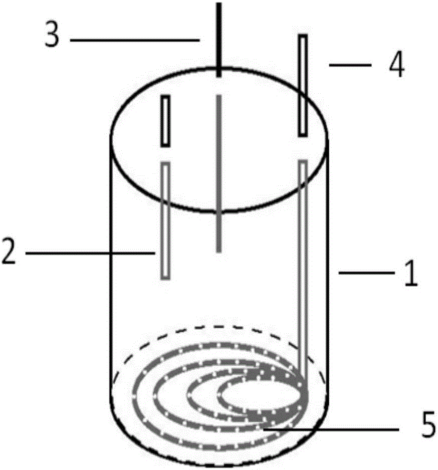
[0042] According to the conditions and steps described in the examples, such as figure 2 As shown, the disperser is spread flatly at the bottom of the reaction pool, and the disperser is of the collar type. The shell of the reaction pool is thick-walled (such as ARC, C80), and the calorimetric equipment is the cumulative heat flow type. The porosity of the porous disperser is 5%, and the volume occupied by the porous disperser is 4% of the volume of the reaction tank.

Embodiment 3

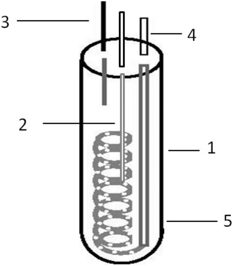
[0044] According to the conditions and steps described in the examples, such as image 3 As shown, the disperser is spirally distributed in the space of the reaction pool, and the disperser is a ring type. The porosity of the porous disperser is 10%, and the volume occupied by the porous disperser is 5% of the volume of the reaction tank.


PUM

PropertyMeasurementUnit
porosityaaaaaaaaaa
porosityaaaaaaaaaa
porosityaaaaaaaaaa

Abstract

The invention relates to a calorimetric pool for uniformly adding a mobile phase in a calorimetric apparatus. The problem in the prior art that the existing mixing effect is not good can be mainly solved. According to the technical scheme of the invention, the calorimetric pool for uniformly adding the mobile phase in the calorimetric apparatus is provided. The calorimetric pool comprises a reaction tank shell, temperature and pressure sensor probes, a stationary phase sample inlet port, a mobile phase sample inlet channel and a porous disperser. The top of a reaction tank is provided with a sleeve. The temperature sensor probe is placed within the internally recessed sleeve and is not in direct contact with a sample. The pressure sensor probe is arranged in a gas-phase space at the top of the reaction tank. The stationary phase sample inlet port is arranged at the top of the reaction tank. The mobile phase sample inlet channel is arranged at the top of the reaction tank. One end of the mobile phase sample inlet channel, extending into the interior of the reaction tank, is connected with the porous disperser. The porous disperser is tiled flat to be distributed at the bottom of the reaction tank or is distributed in the space of the reaction tank in the spiral rising manner. According to the technical scheme of the invention, the above problem can be well solved. The calorimetric pool can be used for calorimetry test.

Description

technical field [0001] The invention relates to a calorimetric cell for uniformly adding mobile phases in calorimetric equipment. Background technique [0002] To evaluate the thermal risk of a specific process, it is necessary to obtain parameters such as heat release rate, heat release, adiabatic temperature rise, and adiabatic pressure rise, and these parameters must be obtained through calorimetric testing. Commonly used calorimeters mainly include ideal heat flow calorimeters (C80, C600, DSC, etc.) and cumulative heat flow calorimeters (ARC, VSP2, etc.). [0003] There are generally two types of objects for calorimetric testing: the heat of phase transition of a single substance, the heat of decomposition, the heat of mixing of multiple substances, and the heat of chemical reactions. Among them, the mixing of multiple substances often involves the mixing of mobile phase (gas phase, liquid phase) and stationary phase (liquid phase or liquid-solid mixture). [0004] Tak...

Claims


Application Information

Patent Timeline
Patent Type & Authority Applications(China)
IPC IPC(8): G01K17/00G01N25/48
CPCG01K17/00G01N25/4873G01N25/488
Inventor 朱红伟孙冰王婷石宁
Owner CHINA PETROLEUM & CHEM CORP
Learn More