
Side-pumping middle-infrared band fiber pumping signal beam combiner

A pumping signal, infrared band technology, applied in lasers, laser parts, phonon exciters, etc., can solve the problems of high technical difficulty, prominent thermal management problems, huge differences, etc., and achieve the effect of high coupling efficiency

Inactive Publication Date: 2017-01-04
NAT UNIV OF DEFENSE TECH
View PDF3 Cites 7 Cited by
  • Summary
  • Abstract
  • Description
  • Claims
  • Application Information

AI Technical Summary

Problems solved by technology

Among the above two mid-infrared low-loss optical fibers, although the loss of the soft glass optical fiber in the 2.4-3.5 μm band is slightly lower than that of the germanium dioxide optical fiber, due to the transition temperature of the soft glass material (below 300°C) and the transformation of the quartz material The temperature (about 1100°C) has a huge difference. It is technically difficult to make a beam combiner together with soft glass optical fiber and quartz optical fiber. At the same time, the low transition temperature of soft glass material makes it difficult for the beam combiner to work at a higher temperature. Therefore, the problem of thermal management is prominent; in contrast, the transition temperature of germanium dioxide material is similar to that of quartz material, so it is more suitable for cooperating with silica optical fiber to make fiber combiners in the mid-infrared band

Method used


Image

  • Side-pumping middle-infrared band fiber pumping signal beam combiner
  • Side-pumping middle-infrared band fiber pumping signal beam combiner
  • Side-pumping middle-infrared band fiber pumping signal beam combiner

Examples


Embodiment Construction

[0025] specific implementation plan

[0026] The following will clearly and completely describe the technical solutions in the embodiments of the present invention with reference to the accompanying drawings in the embodiments of the present invention. Obviously, the described embodiments are only some, not all, embodiments of the present invention. Based on the embodiments of the present invention, all other embodiments obtained by persons of ordinary skill in the art without creative efforts fall within the protection scope of the present invention.

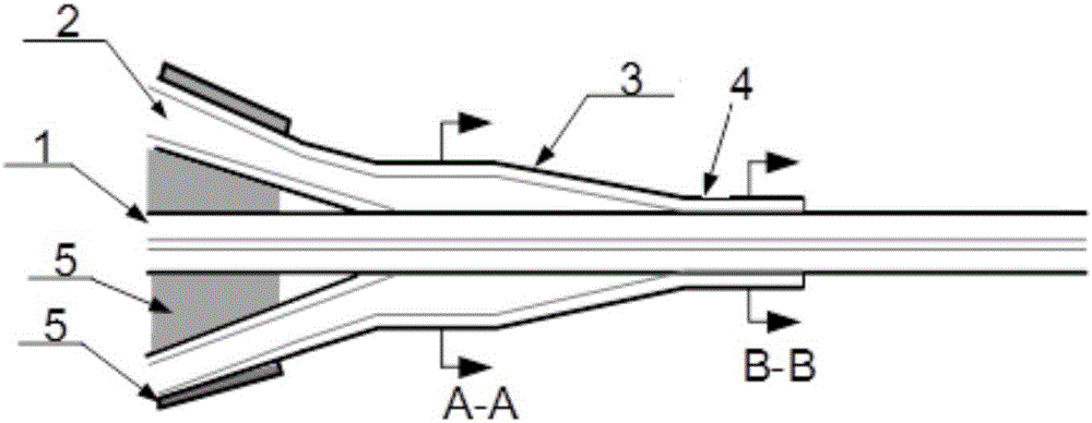
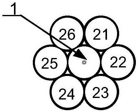
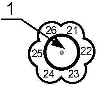
[0027]In this embodiment, one end of the pumping optical fiber 2 is stripped of the coating and the tapered (including the tapered region and the waist region) is fused, and any section of the signal optical fiber 1 except the end is selected to strip the coating, and then the One end of the fused tapered end of the pumping optical fiber 2 is in close contact with the stripped coating layer of the signal optical fiber 1 , and i...


PUM


Abstract

The invention provides a side-pumping middle-infrared band fiber pumping signal beam combiner. The side-pumping middle-infrared band fiber pumping signal beam combiner comprises a signal fiber and a plurality of pumping fibers arranged on the signal fiber. after a coating layer of one end of each pumping fiber is stripped, fused biconical taper is performed, and the end and a part, which is of the signal fiber, with the coating layer being stripped are fixedly connected via melting and solidification. Middle-infrared signal laser and pumping laser respectively enter the signal fiber and the pumping fibers, and through coupling, are output from the other end of the signal fiber. The core of the signal fiber is made of germanium dioxide, and an inner cladding material is a mixed material of germanium dioxide and quartz or a pure quartz material, and therefore, low loss transmission of middle-infrared signal light in the band of 2.7-3.1[mu]m in the fiber core is achieved, and low loss transmission of pumping light in an inner cladding layer is achieved. Coupling efficiency can be controlled not less than 98%, passing rate of the signal light is not less than 99%, pumping laser of more than one hundred watts can be coupled to output fibers, and a high power middle-infrared fiber amplifier is achieved.

Description

technical field [0001] The invention relates to an optical fiber pumping-signal combiner, in particular to a side-pumped mid-infrared band optical fiber pumping signal combiner. Background technique [0002] In recent years, fiber lasers in the mid-infrared band have played an increasingly important role in the fields of environmental monitoring, meteorological detection, biomedicine, material processing, and national defense security. In recent years Er 3+ 、Ho 3+ and Dy 3+ ZBLAN fiber doped with rare earth ions (a kind of fluoride fiber, the specific component is ZrF 4 -BaF 2 -LaF 3 -AlF 3 The rapid development of -NaF) has made many domestic and foreign research institutes report mid-infrared lasers with output power in the order of watts (see S.D.Jackson, Towards high-powermid-infrared emission from a fiber laser, Nature Photonics, 6(7) , 423-431(2012). (S.D.Jackson, Towards high-power mid-infrared fiber laser output, Nature Photonics, 2012, Issue 6 Vol. 7)). Thes...

Claims


Application Information

Patent Timeline
Patent Type & Authority Applications(China)
IPC IPC(8): H01S3/067
CPCH01S3/06708H01S3/06716H01S3/06733H01S3/06754
Inventor 张斌杨林永殷科侯静陈胜平陈子伦李志鸿姚金妹雷成敏刘广琛蔡振
Owner NAT UNIV OF DEFENSE TECH
Learn More