Perfusion and dilation balloon system

A technique for dilating balls and balloons, which is applied in the direction of balloon-shaped catheters and catheters to achieve the effect of interventional and surgical treatment

Pending Publication Date: 2017-01-11
苗立夫
View PDF8 Cites 6 Cited by
  • Summary
  • Abstract
  • Description
  • Claims
  • Application Information

AI Technical Summary

Problems solved by technology

[0004] At present, in addition to drugs to reduce myocardial oxygen consumption, stabilize plaque, inhibit platelet function, and monitoring methods, the above-mentioned patients with severe coronary ostium stenosis have no better treatment before undergoing coronary artery bypass grafting in cardiac surgery. Coronary blood flow and myocardial perfusion safeguards

Method used


Image

  • Perfusion and dilation balloon system
  • Perfusion and dilation balloon system
  • Perfusion and dilation balloon system

Examples


Embodiment 1

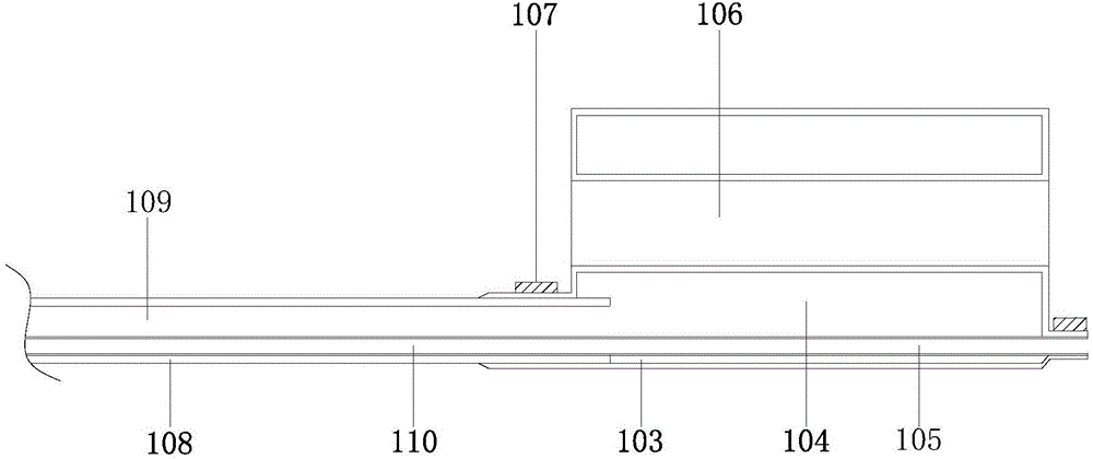
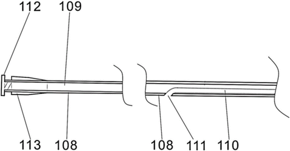
[0027] Embodiment 1: as Figure 1-3 As shown, the present invention provides a perfusion dilation balloon system, comprising: a perfusion dilation balloon 103 and a delivery catheter 108 connected to the rear of the perfusion dilation balloon 103;

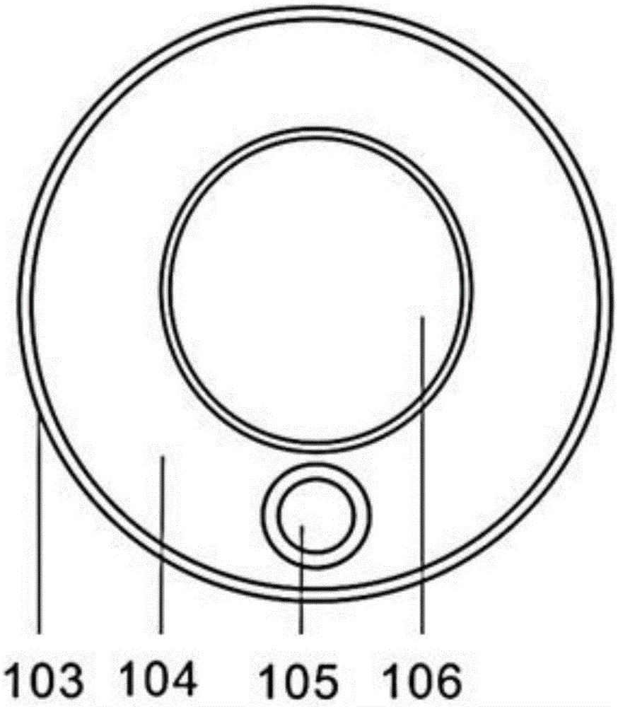
[0028] The perfusion expansion balloon 103 is hollow cylindrical after expansion; the perfusion expansion balloon 103 is provided with a perfusion cavity 106 for perfusion of blood flow, and the perfusion cavity 106 is hollow (that is, the perfusion expansion balloon 103 has a perfusion cavity 106 hollow cylinder-like balloon); the axis of the perfusion cavity 106 after the expansion of the perfusion expansion balloon 103 is parallel to the axis of the perfusion expansion balloon 103; the perfusion cavity 106 forms a closed balloon pressure cavity with the wall of the perfusion expansion balloon 103 104 , the balloon pressure cavity 104 is provided with a balloon guide wire cavity 105 , and the axis of the balloon guide wire cavity...

Embodiment 2

[0037] Embodiment 2: as Figure 4 As shown, the perfusion and dilation balloon system provided by the present invention is placed at the opening of the left coronary artery, and the balloon pressure chamber 104 is filled with a certain pressure of liquid through the catheter pressure chamber 109, and the inner diameter and outer diameter of the perfusion and dilation balloon 103 are expanded to form a The perfusion cavity 106 is a hollow cylinder to ensure blood perfusion in the left coronary artery.

[0038] Through the above technical scheme, the perfusion and expansion balloon system provided by the present invention is placed at the mouth of important branches of large blood vessels, and the expansion of the perfusion and expansion balloon can play the role of squeezing the plaque toward the outer wall of the blood vessel, expanding the lumen and supporting the vessel wall , and at the same time perfuse the perfusion cavity inside the expansion balloon to ensure the blood ...


PUM


Abstract

The invention discloses a perfusion and dilation balloon system. The perfusion and dilation balloon system comprises a perfusion and dilation balloon and a delivery conduit, wherein a perfusion chamber for pouring blood flow is arranged on the perfusion and dilation balloon; a closed balloon pressure chamber is formed by the infusion chamber and the perfusion and dilation balloon; a balloon wire guiding chamber is arranged in the balloon pressure chamber; a conduit pressure chamber communicated with the balloon pressure chamber is arranged in the delivery conduit; a conduit wire guiding chamber communicated with the balloon wire guiding chamber is arranged in the conduit pressure chamber. According to the perfusion and dilation balloon system disclosed by the invention, the balloon pressure chamber is filled with liquid with a certain pressure to dilate the perfusion and dilation balloon, thus forming a hollow cylindrical pipeline body; the hollow perfusion chamber guarantees the perfusion of the blood blow while blood vessel walls are supported and dilated by a balloon wall of the perfusion and dilation balloon; when serious lesion of blood vessel openings, aortic dissecting aneurysm and main blood vessel opening occur, effective blood flow perfusion channels can be effectively provided for important blood vessel opening parts and corresponding visceral organs, thereby guaranteeing further intervention and surgical treatment.

Description

technical field [0001] The invention relates to the technical field of medical intervention consumables, in particular to a perfusion and expansion balloon system. Background technique [0002] Vascular stenosis and occlusion are diseases with high morbidity and mortality. For vascular diseases, especially arteriosclerosis, stenosis and occlusion diseases, vascular lesion balloon dilatation and stent implantation are one of the main treatment methods. The expandable balloon is delivered to the lesion, and the diameter of the lumen of the vessel is enlarged by filling and expanding the balloon to squeeze the plaque outside the blood vessel, and finally, a stent is implanted in the lesion to support the lumen to achieve the purpose of treating vascular stenosis. [0003] In the case of vascular lesions in special clinical parts, such as spontaneous or iatrogenic aortic dissection involving the ostium of main branch arteries such as coronary arteries, renal arteries, and commo...

Claims


Application Information

Patent Timeline
Patent Type & Authority Applications(China)
IPC IPC(8): A61M25/10
CPCA61M25/104
Inventor 苗立夫
Owner 苗立夫
Why Eureka
Try Eureka