
Laser peening straightening method and device for deformed blade

A laser shot peening and shape correction technology, used in laser welding equipment, welding equipment, metal processing equipment, etc., can solve the problems of difficult control of grinding accuracy, complicated numerical control program writing, secondary damage of blades, etc., to improve anti-fatigue damage. Ability, control process is simple and reliable, and the effect of improving work efficiency

Active Publication Date: 2017-01-11
GUANGDONG UNIV OF TECH
View PDF6 Cites 15 Cited by
  • Summary
  • Abstract
  • Description
  • Claims
  • Application Information

AI Technical Summary

Problems solved by technology

[0003] Most of the current aero-engine blades are manufactured by CNC milling machines. Due to the existence of processing stress and deformation, the blades are easily scrapped due to the out-of-tolerance twist angle during the manufacturing process; Can be hit by foreign objects, both of which can easily deform and twist the blades
The profile of the blade is complex, and it is extremely difficult for the deformed thin-walled blade to restore its required profile size. The blade that is seriously deformed or damaged can be replaced directly, but the procurement cost of new blades is high, and the procurement cycle is long, which is easily restricted; The replaced deformed thin-walled blades usually adopt CNC grinding and manual grinding
CNC grinding mainly relies on multi-axis linkage abrasive belt grinders. This method has high equipment investment costs and complicated CNC program writing; although manual grinding is low in cost and simple in equipment, it requires too high technical requirements for fitters, and the grinding accuracy is difficult to control, which is easy to cause damage to the blades. secondary injury

Method used


Image

  • Laser peening straightening method and device for deformed blade
  • Laser peening straightening method and device for deformed blade
  • Laser peening straightening method and device for deformed blade

Examples


Embodiment Construction

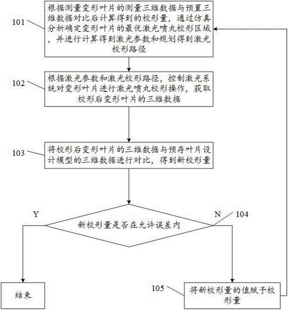
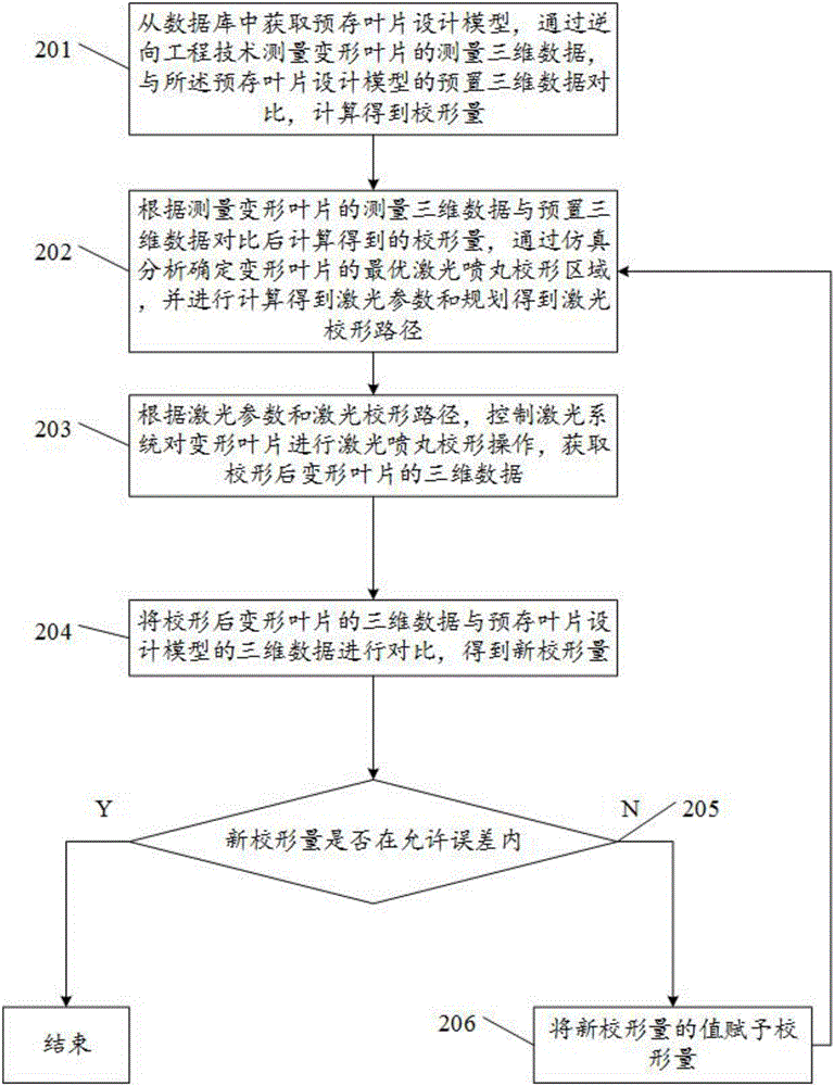
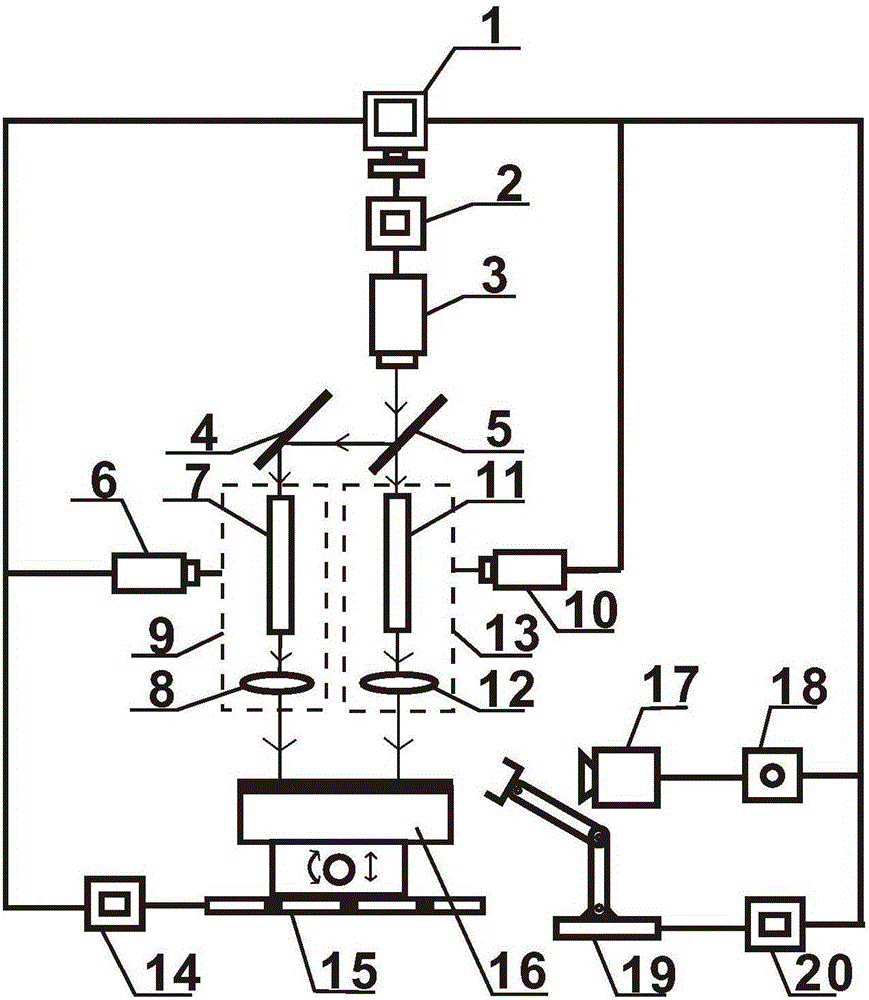
[0041]The embodiment of the present invention provides a method and device for laser peening shape correction of deformed blades. Double laser beams are used to carry out shape correction work from both ends of the shape correction path, which can shorten the shape correction time by half and improve work efficiency; The pill shape can generate residual compressive stress inside the blade, improve the fatigue resistance and corrosion resistance of the blade, and increase the strength of the blade; the blade deformation control process is simple and reliable, the cost is low, and it is easy to realize automation, which meets the requirements of precision manufacturing of aviation parts. It is especially suitable for the precise shape correction of deformed blades with out-of-tolerance torsion angles.

[0042] In order to make the purpose, features and advantages of the present invention more obvious and understandable, the technical solutions in the embodiments of the present in...


PUM


Abstract

The embodiment of the invention discloses a laser peening straightening method and device for a deformed blade. Straightening is performed from the two ends of a straightening path through two laser beams, so that half of the straightening time can be saved, and the working efficiency can be improved; laser peening straightening can generate residual compressive stress in the blade to improve the fatigue damage prevention capability and the corrosion resistance of the blade, as well as the strength of the blade; and the blade deformation control process is simple and reliable, low in cost and easy to realize automation, conforms to the demand for precision manufacture of aircraft parts and is particularly suitable for precision straightening of the deformed blade with an out-of-tolerance torsion angle.

Description

technical field [0001] The invention relates to the field of laser shot peening shape correction, in particular to a laser shot peening shape correction method and device for deformed blades. Background technique [0002] Laser peening technology is a new type of material forming and strengthening technology. The high-energy-density laser can generate a shock wave pressure of up to several gigaPascals (GPa) on the metal surface, which can not only deform the metal, but also make the metal obtain high The residual compressive stress layer greatly improves the fatigue life of the metal. Compared with mechanical shot peening, the residual compressive stress layer is deeper. In the early 21st century, the United States applied laser peening technology to the strengthening and remanufacturing of aero-engine blades. [0003] Most of the current aero-engine blades are manufactured by CNC milling machines. Due to the existence of machining stress and deformation, the blades are easi...

Claims


Application Information

Patent Timeline
IPC IPC(8): B23K26/356B23K26/18B23K26/08B23K26/70
CPCB23K26/0861B23K26/0876B23K26/18B23K26/356B23K26/702
Inventor 张永康杨青天杨智帆
Owner GUANGDONG UNIV OF TECH
Learn More