Double-face polishing machine for large-caliber optical element

A technology for double-sided polishing machines and optical components, which is applied in surface polishing machine tools, optical surface grinders, grinding/polishing equipment, etc. To meet the requirements of double-sided polishing of optical components and other issues, to achieve the effect of improving double-sided polishing accuracy and production efficiency, improving service life and system beam quality, and increasing adjustable process parameters

Inactive Publication Date: 2017-01-11
东莞市兰光光学科技有限公司
View PDF7 Cites 10 Cited by
  • Summary
  • Abstract
  • Description
  • Claims
  • Application Information

AI Technical Summary

Problems solved by technology

Small-scale manufacturing errors on optical surfaces can lead to high-frequency modulation of the beam and nonlinear growth of the system, which can easily cause damage to optical components and reduce the focusable power of the beam
[0003] At present, large-scale ring polishing machines at home and abroad adopt the method of single-sided polishing. The processing accuracy depends on the experience of the operator, and the requirements for the operator are high. When processing an optical element with a transmitted wavefront, only one side can be processed first, and the other One side needs to be protected, which makes it difficult to detect the transmitted wavefront, and the processing efficiency is low; the existing domestic double-sided polishing machine is mainly for small and medium-sized ultra-thin optical components with a diameter of 80-300mm, mainly focusing on the production cycle and production cost, surface shape accuracy, parallelism The precision requirements are generally not high, and cannot meet the requirements for double-sided polishing of optical components with a diameter of 600mm
Patent 2010101454338 proposes a ring and pendulum polishing double-sided polishing machine, which integrates ring and pendulu

Method used


Image

  • Double-face polishing machine for large-caliber optical element
  • Double-face polishing machine for large-caliber optical element

Examples


Embodiment Construction

[0016] Below in conjunction with embodiment the present invention is further described.

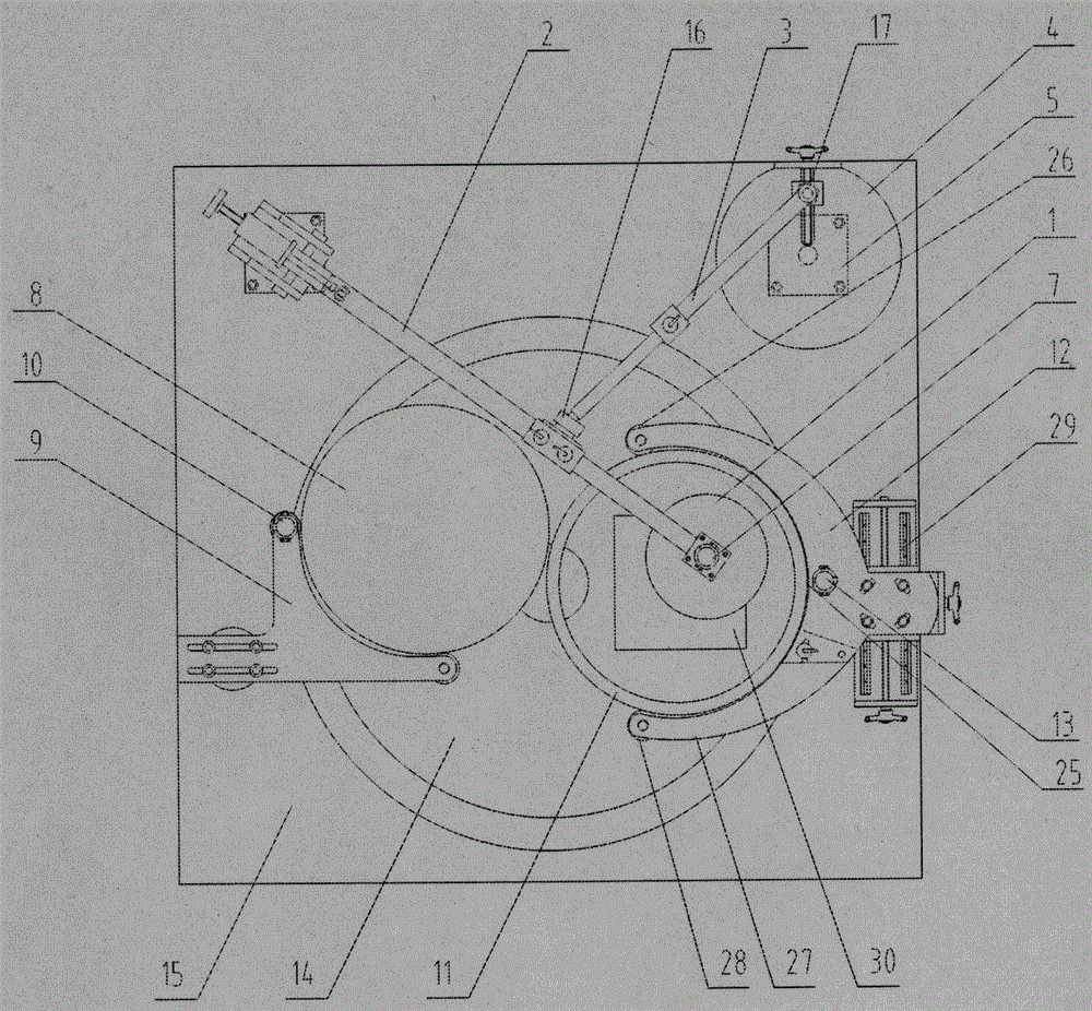
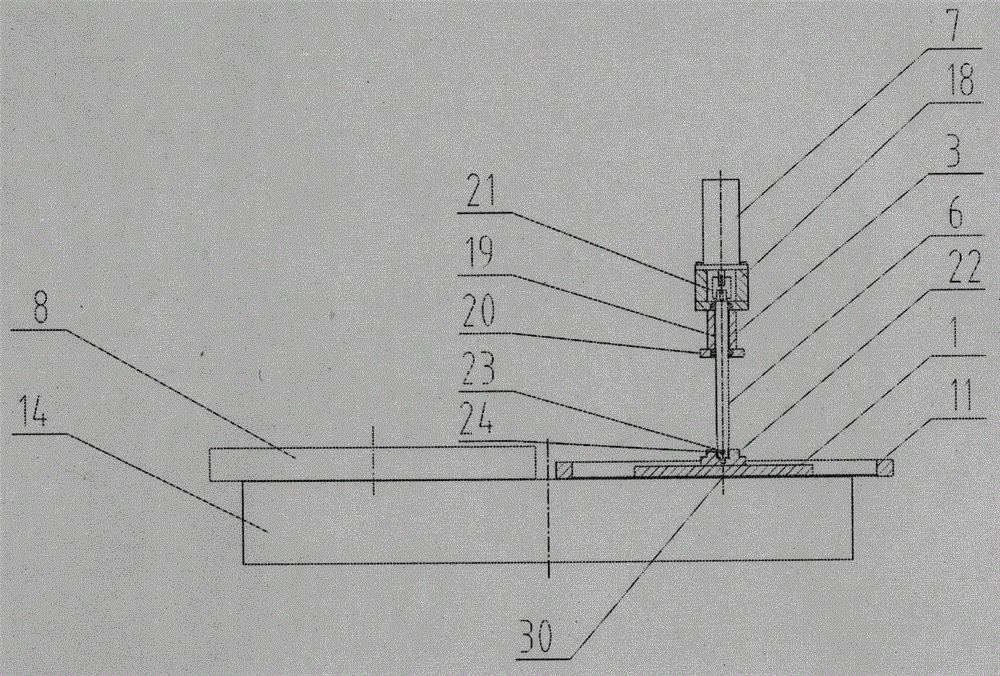
[0017] Such as Figure 1-2 , a double-sided polishing machine for large-diameter optical components, comprising: an upper polishing disc 1, a main swing rod 2, an auxiliary swing rod 3, an eccentric wheel 4, an eccentric wheel base 5, an upper polishing disc rotation shaft 6, and an upper polishing disc driving motor 7. Calibration disc 8, calibration disc caliper 9, calibration disc drive motor 10, workpiece ring 11, workpiece ring caliper 12, workpiece ring drive motor 13, lower polishing disc 14, main base 15; among them, main pendulum 2, auxiliary pendulum Rod 3, eccentric wheel 4, and eccentric wheel base 5 form the swing structure of the upper polishing disc to provide swinging motion for the upper polishing disc; one end of the main swing rod 2 is provided with the rotation axis 6 of the upper polishing disc, the driving motor 7 of the upper polishing disc, and the upper polishing ...


PUM


Abstract

The invention discloses a double-face polishing machine for a large-caliber optical element, and belongs to the technical field of optical element machining. An upper polishing disc structure capable of swinging and rotating is adopted, an upper polishing disc carries out swing polishing and annular polishing on a workpiece at the same time, the polishing efficiency is improved, the polishing track becomes more uniform, and the problem that side treading and corner uplifting are likely to appear in the surface shape is solved; a lower polishing disc carries out annular polishing on the lower surface of the workpiece, a correction disc is adopted to carry out correction keeping on the surface shape of the lower polishing disc, the surface shape precision of the polishing discs is improved, the surface shape precision of the optical element is improved, and the small-size manufacturing error of the optical surface can be reduced; an adjustable clamp structure is adopted, adjustable technology parameters are increased, the polishing rack is further uniform, and the double-face polishing precision and the production efficiency are improved; the polishing machine is suitable for double-face polishing of the large-caliber optical element with the caliber reaching 600 mm and the special requirements for the depth of parallelism, reflective wavefront and transmission wavefront.

Description

technical field [0001] The invention belongs to the technical field of optical element processing, in particular to a double-sided polishing machine for large-diameter optical elements. Background technique [0002] With the development of modern optical systems, especially the rapid development of high-power laser devices, higher requirements are placed on the processing of large-diameter optical components. In addition to strict requirements on surface shape accuracy, parallelism, production cycle and production cost, small-scale manufacturing errors of optical surfaces have also attracted more and more attention. Small-scale manufacturing errors on optical surfaces can lead to high-frequency modulation of the beam and nonlinear growth of the system, which can easily cause damage to optical components and reduce the focusable power of the beam. [0003] At present, large-scale ring polishing machines at home and abroad adopt the method of single-sided polishing. The proce...

Claims


Application Information

Patent Timeline
IPC IPC(8): B24B29/02B24B13/00B24B41/02B24B41/06
CPCB24B29/02B24B13/00B24B41/02B24B41/06
Inventor 毛卫平张清明刘秦江
Owner 东莞市兰光光学科技有限公司
Why Eureka
Try Eureka