Ceramic slurry injection forming system

A technology of grouting molding and ceramics, which is applied in the direction of ceramic molding machines, ceramic molding workshops, auxiliary molding equipment, etc., can solve the problems of easy damage of plaster, high labor intensity, and generation of air bubbles, so as to avoid damage to plaster molds and have a high degree of automation , the effect of reducing the detection error

Active Publication Date: 2017-01-11
QUANZHOU KUNTAI MACHINERY PRECISION MFG CO LTD
View PDF1 Cites 15 Cited by
  • Summary
  • Abstract
  • Description
  • Claims
  • Application Information

AI Technical Summary

Problems solved by technology

However, the current grouting molding is a single manual operation, which has high labor intensity and low production efficiency.
[0003] Patent No. CN202964845U provides a high degree of mechanization, reduced labor intensity, and high production efficiency of a ceramic hollow pot type grouting molding automatic production line, although the molding process is mechanized, but after the grouting is finished Due to various reasons, the plaster mold may not be filled with mud, so that the product size and thickness are inconsistent; after the grouting, the plaster mold needs to be turned over to pour out the excess mud, but the plaster molded in the plaster mold is easily damaged during the turning process , and the process of pouring out the mud will cause the production site to be relatively messy, and because the grouting pipe is far away from the plaster mold during the grouting process, when the mud is injected into the mold, it will collide with each other and it is easier to cause air to be mixed in the mud and generate air bubbles, although There is an automatic mold rotation device to rotate the plaster mold to eliminate air bubbles, but the efficiency is low, and it cannot be guaranteed to completely eliminate air bubbles, resulting in unstable product quality

Method used


Image

  • Ceramic slurry injection forming system
  • Ceramic slurry injection forming system
  • Ceramic slurry injection forming system

Examples


Embodiment Construction

[0031]In order to make the technical means, creative features, goals and effects achieved by the present invention easy to understand, the following embodiments will specifically illustrate the ceramic slip casting system of the present invention in conjunction with the accompanying drawings.

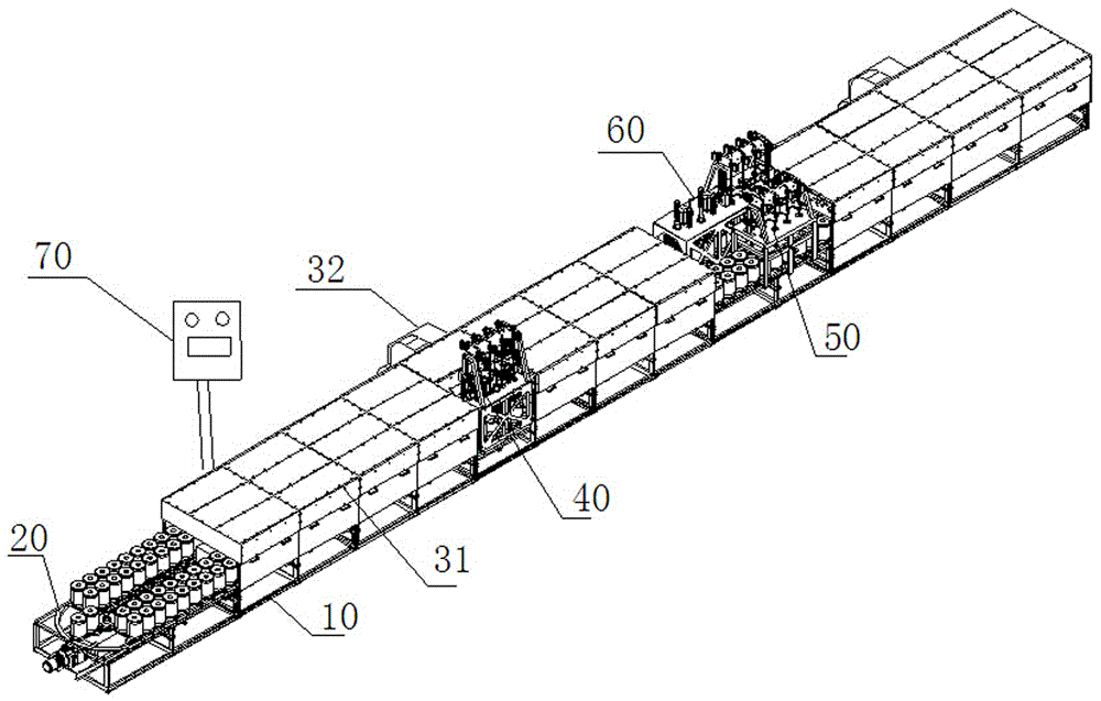
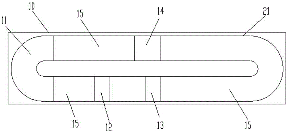
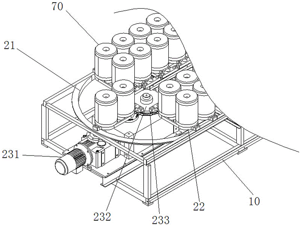
[0032] like figure 1 As shown, the ceramic slip casting system includes: a support part 10 , a conveying device 20 , a drying device, a grouting device 40 , a grouting device 50 , a desizing device 60 and a control device 70 . The support part 10 is used to support each device, the conveying device 20, the drying device, the grouting device 40, the grouting device 50, and the grouting device 60 are all installed on the support part 10, the drying device 30 is covered on the conveying device 20, and the grouting The device 40, the grout replenishing device 50, and the grout removing device 60 are sequentially arranged along the conveying path of the plaster mold. The control device 70 i...


PUM


Abstract

The invention provides a ceramic slurry injection forming system. When a slurry injection device injects slurry into a plaster mold, a movable supporting pipe rises up from the bottom of the plaster mold while being subjected to slurry injection, so that the phenomenon that air is mixed in slurry due to mutual collision of the slurry can be avoided during slurry injection; meanwhile, a rotating part drives the plaster mold to rotate to enable the slurry in the plaster mold to be uniformly distributed; a slurry supplementation device supplements the slurry to the plaster mold, so that the phenomenon of unstable size and thickness of a product due to the fact that the plaster mold is not full of the slurry because of various reasons in the slurry injection device is avoided; a drying device enables the plaster mold to absorb the slurry for forming; a main pipe in a slurry extraction part is connected with a vacuum pump, so that residual slurry in the plaster mold can be extracted; a slurry throwing part drives the plaster mold to move, so that a little of slurry extracted from the bottom of the plaster mold is thrown to the inner wall of the plaster mold so as to be absorbed by the inner wall; and therefore, the ceramic slurry injection forming system provided by the invention is high in automation degree and high in product quality, and is relatively clean in production and high in production efficiency.

Description

technical field [0001] The invention belongs to the technical field of ceramic molding equipment, and in particular relates to a ceramic grouting molding system. Background technique [0002] Slip casting is an ancient and traditional ceramic molding method, which is widely used. All utensils with complex shapes, irregular shapes, thin walls, large volumes and loose size requirements can be formed by grouting. Including general daily-use ceramic vases, soup bowls, dish plates, teapots, sanitary ware toilets, washbasins, craft porcelain of various shapes, and a considerable number of industrial ceramics and special ceramic products. However, the current grouting molding is a single manual operation, which has high labor intensity and low production efficiency. [0003] Patent No. CN202964845U provides a high degree of mechanization, reduced labor intensity, and high production efficiency of a ceramic hollow pot type grouting molding automatic production line, although the m...

Claims


Application Information

Patent Timeline
Patent Type & Authority Applications(China)
IPC IPC(8): B28B1/26B28B15/00B28B17/00
CPCB28B1/26B28B1/264B28B15/00B28B17/00
Inventor 柯国镇蔡理昌陈志滨操奇勋颜明哲
Owner QUANZHOU KUNTAI MACHINERY PRECISION MFG CO LTD
Why Eureka
Try Eureka