Negative pressure heat pump drying device and working method thereof

A heat pump drying and negative pressure technology, applied in drying, dryer, drying gas arrangement and other directions, can solve the problems of energy loss, large energy consumption, etc., and achieve convenient operation, low energy consumption and wide application range. Effect

Inactive Publication Date: 2017-01-11
浙江意而创新能源科技有限公司
View PDF1 Cites 3 Cited by
  • Summary
  • Abstract
  • Description
  • Claims
  • Application Information

AI Technical Summary

Problems solved by technology

In addition, the patent with the notification number CN204346019U also discloses an air source heat pump drying room with the air inlet of the evaporator as the new air outlet of the drying room. This solution has the functions of dehumidification and dehumidification. The inner cavity expands the drying capacity and energy-saving potential of the drying room to solve the problem of energy loss in the drying process of the existing dehumidification and dehumidification heat pump dryers
However, the above-mentioned existing heat pump dryers all realize dehumidification and / or dehumidification under normal pressure. When the drying room is heated, the air strength in the drying room does not change. Temperature or liquefaction temperature, large energy consumption

Method used


Image

  • Negative pressure heat pump drying device and working method thereof
  • Negative pressure heat pump drying device and working method thereof

Examples


Embodiment 1

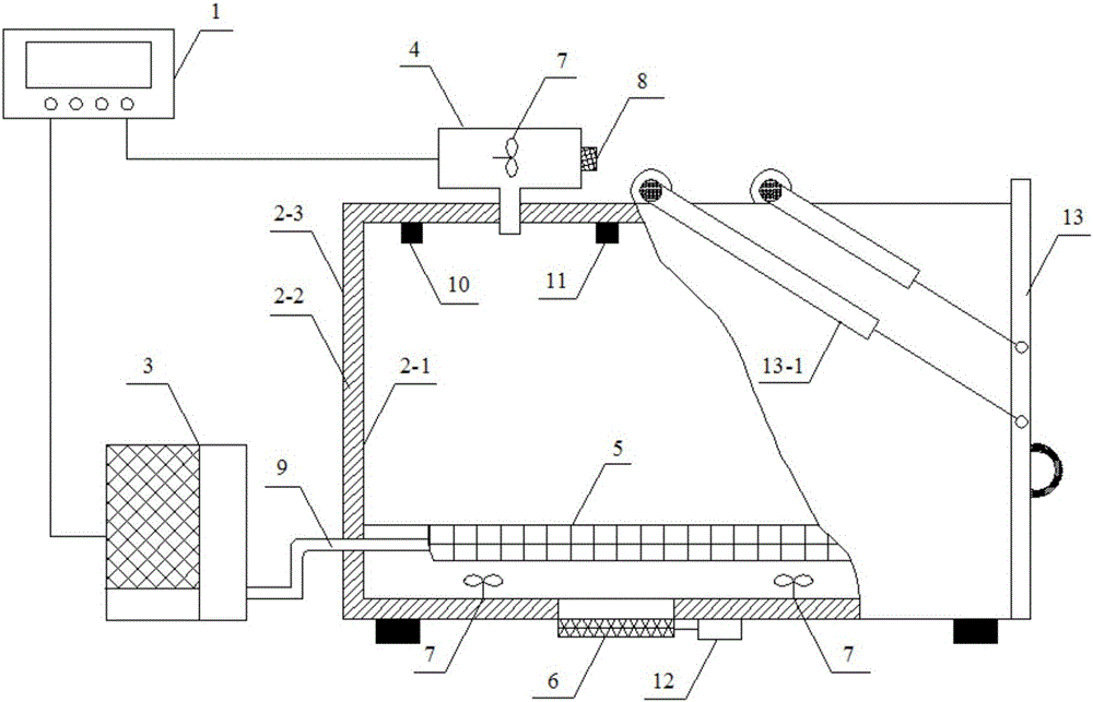
[0024] Such as figure 1 As shown, this embodiment discloses a negative pressure heat pump drying device and its working method, including a microcomputer controller 1, a drying room 2, a heat pump host 3, an air extractor 4, a condenser 5, an air inlet door 6, and an air inlet door Motor 12, three circulation fans 7, pressure sensor 10 and temperature sensor 11.

[0025] Drying room 2 is made up of three-sided drying room body and dodge door 13, and drying room body is made up of a box-type box body by inner layer 2-1, insulation layer 2-2 and outer layer 2-3, and dodge door 13 is included on it The provided spring pull rod 13-1. The heat pump host 3 is arranged outside the drying room 2, and the heat pump host 3 is connected to the condenser 5 arranged inside the drying room 2 through the refrigerant circulation pipe 9, and the condenser 5 is arranged at the lower half of the inside of the drying room 2; the air inlet door 6 is set At the bottom of the drying room 2, two ci...

Embodiment 2

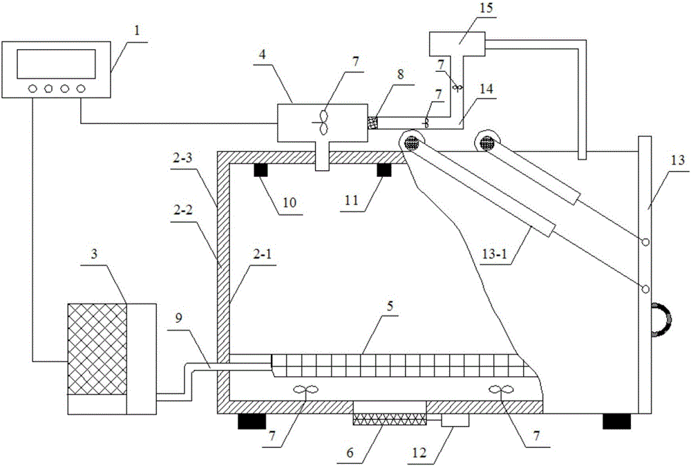
[0033] Such as figure 2 As shown, different from Embodiment 1, this embodiment also includes an exhaust pipe 14 and an evaporator 15, one end of the exhaust pipe 14 is connected to the exhaust port 8, and two circulating fans are arranged in the exhaust pipe 14 7. The circulation fan 7 is electrically connected to the microcomputer controller 1, the evaporator 15 is connected to the other end of the exhaust pipe 14, and the evaporator 15 is connected to the drying room 2. The exhaust pipe 14 is connected to the exhaust port 8, and the exhaust pipe 14, under the action of the circulating fan 7, introduces the high-temperature water vapor discharged from the drying room 2 into the evaporator 15, and the evaporator 15 releases heat from the high-temperature water vapor Liquefied into liquid and discharged, and at the same time, the heat released by liquefaction is introduced into the drying room 2 for heating, so as to maximize energy utilization.


PUM


Abstract

The invention discloses a negative pressure heat pump drying device and a working method of the negative pressure heat pump drying device. A heat pump and an air exhauster are synchronously started, the air exhauster exhausts air in a drying room, and air pressure in the drying room is decreased to be lower than ambient atmosphere pressure, so that the boiling point of water in materials located in the drying room is decreased, and negative pressure drying is achieved. Compared with an existing technical scheme of asynchronous start of the heat pump and the air exhauster, the mechanism of an original drying device does not need to be changed, operation is convenient, and meanwhile the negative pressure heat pump drying device has the advantages of being small in energy consumption, high in material drying speed, wide in application range and the like.

Description

[0001] 【Technical field】 [0002] The invention belongs to the field of drying, and in particular relates to a negative pressure heat pump drying device for drying materials. [0003] 【Background technique】 [0004] Drying refers to the process of evaporating and taking away the moisture in the material by introducing hot air. It is widely used in tobacco, agricultural and sideline products, medicinal materials, food, textile, chemical industry, electroplating, urban public utilities, heating, slaughtering, breeding, hotels, schools , hospitals, engineering and other industries and fields. The evaporation and drying process of heating the moisture in the material from the liquid state to the gaseous state consumes a lot of energy. According to incomplete statistics, the energy consumed by drying materials in most developed countries accounts for 7% to 15% of the total energy consumption in the country, while The thermal efficiency is only 20% to 50%, and the energy consumption...

Claims


Application Information

Patent Timeline
Patent Type & Authority Applications(China)
IPC IPC(8): F26B9/06F26B21/06F26B25/00
Inventor 潘永良代长江刘在祥
Owner 浙江意而创新能源科技有限公司
Why Eureka
Try Eureka