
Engine thermal energy recovery generating set

A heat recovery and power generation device technology, applied in the direction of internal combustion piston engines, noise reduction devices, exhaust devices, etc., can solve the problems of wasting resources, wasting, and wasting energy, and achieve the effects of simple structure, realization of recycling, and convenient deployment and implementation

Inactive Publication Date: 2017-01-18
温后东
View PDF6 Cites 11 Cited by
  • Summary
  • Abstract
  • Description
  • Claims
  • Application Information

AI Technical Summary

Problems solved by technology

[0003] As we all know, the internal combustion engine will discharge a large amount of exhaust gas in the process of doing work. At present, the efficiency of the gasoline engine is 25% to 35%, while the efficiency of the diesel engine is 35% to 45%. Most of the remaining energy comes from the internal combustion engine in the form of exhaust gas. It is exhausted and wasted, and the utilization of this part of heat energy is seldom in the prior art
In order to meet the emission standards of exhaust gas, it is even necessary to install a three-way catalytic converter containing rare and precious metals, which not only wastes energy in vain, but also wastes a certain amount of resources
Since the waste heat resources in the tail gas are generally discharged for a long time, the accumulation is actually a very considerable amount of energy, but there is a lack of application for the recovery and utilization of this part of energy in the prior art

Method used


Image

  • Engine thermal energy recovery generating set
  • Engine thermal energy recovery generating set
  • Engine thermal energy recovery generating set

Examples


Embodiment Construction

[0030] In order to make the purpose, technical solution and advantages of the present invention clearer, the technical solution of the present invention will be described in detail below. Apparently, the described embodiments are only some of the embodiments of the present invention, but not all of them. Based on the embodiments of the present invention, all other implementations obtained by persons of ordinary skill in the art without making creative efforts fall within the protection scope of the present invention.

[0031] The technical solutions of the present invention will be described in further detail below with reference to the accompanying drawings and embodiments.

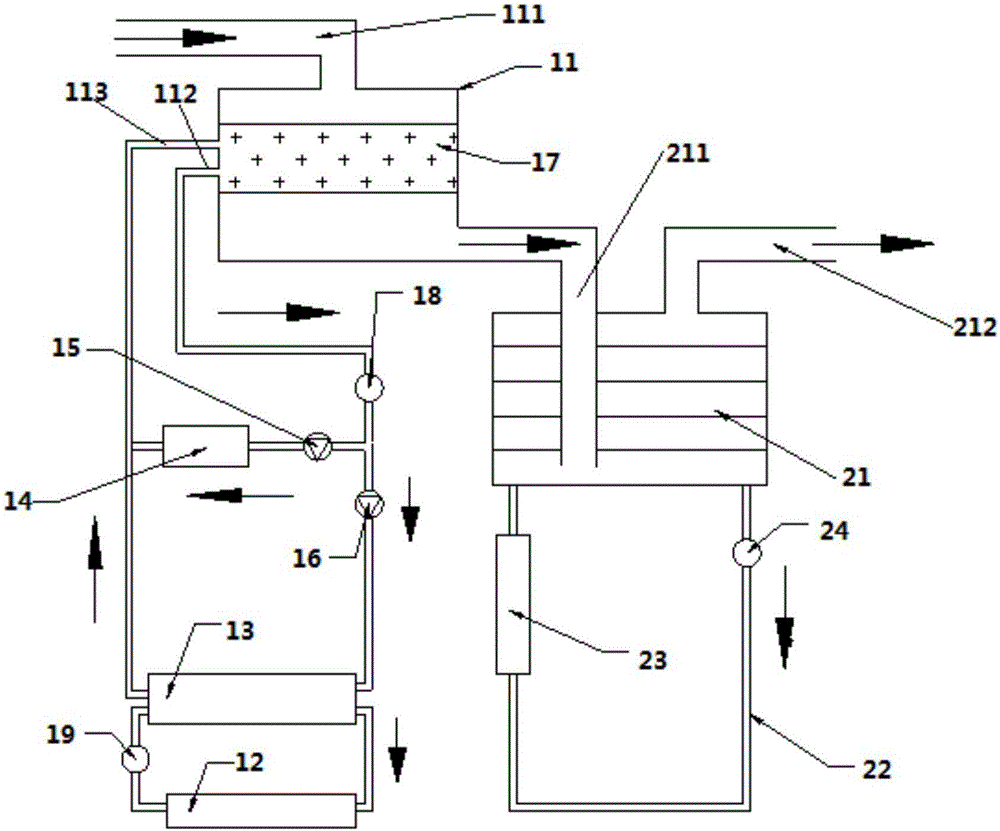
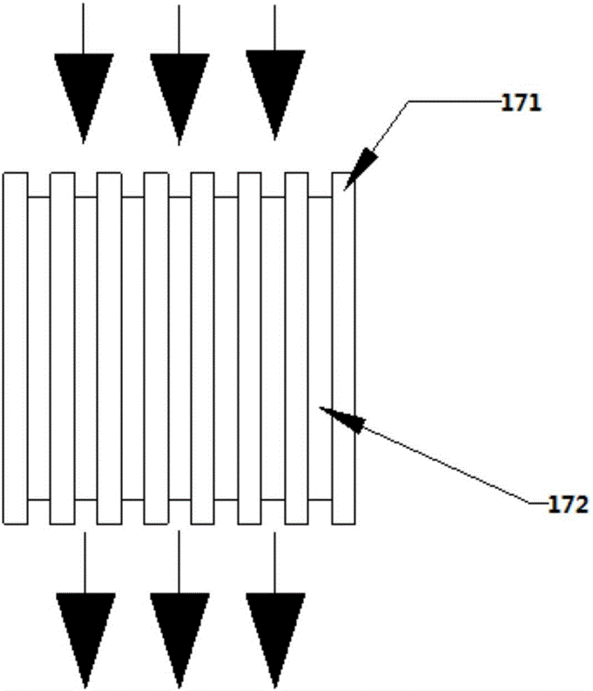
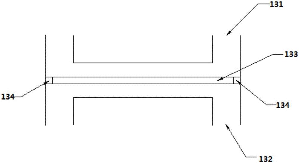
[0032] see figure 1 , a heat recovery power generation device for an internal combustion engine provided by an embodiment of the present invention includes a heat recovery box 11, a cold end radiator 12 and a thermoelectric power generation device 13, wherein,

[0033] The heat recovery box 11 has its ...


PUM


Abstract

The invention relates to a thermal energy recovery power generation device of an internal combustion engine, which comprises a heat energy recovery box, a cold end heat sink and a temperature difference power generation device, among which the heat energy recovery box is connected with an exhaust port of an internal combustion engine, a cooling liquid outlet of the internal combustion engine is connected to a hot end inlet port of the thermoelectric generator through a first pipe, a coolant inlet of the heat energy recovery tank is connected to a hot end outlet port of the thermoelectric generator through a second pipe; the heat energy recovery box is used for absorbing heat of the tail gas discharged from the internal combustion engine to heat the cooling liquid in the heat energy recovery tank; and a water inlet of the cold end radiator is connected to a cold end outlet port of the thermoelectric generator, and a water outlet of the cold end radiator is connected to a cold end inlet port of the thermoelectric generator. By the technical solution of the present invention, recovery and utilization of the engine exhaust gas can be realized.

Description

technical field [0001] The invention relates to the technical field of internal combustion engine heat energy recovery, in particular to an internal combustion engine heat energy recovery power generation device. Background technique [0002] Energy is an indispensable resource for human survival and development, especially because of the discovery, development and utilization of electricity, which greatly promotes the progress of human civilization. Since then, human production and life have become increasingly inseparable from electricity. And power shortages appear at any time in industrially developed areas. In addition to coal, oil, natural gas and other non-renewable high-level resources that can generate electricity, how to fully develop and utilize recyclable low-level energy to generate electricity has become an important research topic in countries around the world today. [0003] As we all know, the internal combustion engine will discharge a large amount of exha...

Claims


Application Information

Patent Timeline
IPC IPC(8): F01N5/02H02N11/00
CPCF01N5/02F01N5/025H02N11/002Y02T10/12
Inventor 温后东
Owner 温后东
Learn More