
Temperature-insensitive magnetic field sensor based on magnetic fluid filling optical fiber microcavity

A magnetic field sensor and magnetic fluid technology, which is applied in the use of magneto-optical equipment for magnetic field measurement, the size/direction of the magnetic field, etc., can solve the problems of low sensor sensitivity, reduced temperature sensitivity, and inability to achieve complete temperature compensation. The effect of large measurement range, compact structure and high sensitivity

Pending Publication Date: 2017-01-18
HARBIN UNIV OF SCI & TECH
View PDF1 Cites 9 Cited by
  • Summary
  • Abstract
  • Description
  • Claims
  • Application Information

AI Technical Summary

Problems solved by technology

However, this method is not conducive to the miniaturization and integration of the sensor, the sensitivity is limited by the FBG measurement sensitivity, and it will shorten the measurement range of the interferometric magnetic field sensor
In addition, the invention patent (Application No. CN 102221679 A) discloses a magnetic field sensor based on ferrofluid-filled photonic crystal fibers. Although the sensitivity to temperature is reduced by using this sensor, complete temperature compensation cannot be achieved, and the sensor has low sensitivity.

Method used


Image

  • Temperature-insensitive magnetic field sensor based on magnetic fluid filling optical fiber microcavity
  • Temperature-insensitive magnetic field sensor based on magnetic fluid filling optical fiber microcavity
  • Temperature-insensitive magnetic field sensor based on magnetic fluid filling optical fiber microcavity

Examples


application example 1

[0041] An application example of the temperature-insensitive magnetic field sensor 100 based on the ferrofluid-filled fiber microcavity of the present invention is described below.

[0042] Under the action of a magnetic field, the magnetic fluid will produce a magnetorefractive effect, and its refractive index will change with the change of the magnetic field, which will lead to a change in the optical path of the fiber microcavity, thereby causing the interference spectrum of the fiber microcavity to translate. By detecting the interference spectrum The magnitude of the translation can obtain the magnitude of the measured magnetic field.

[0043] Broad-spectrum light source 1-1 adopts ASE light source, and its spectral range is 1300nm-1600nm. The broad-spectrum light emitted passes through 1×2 fiber coupler (as an example of fiber coupler 1-2) and then enters sensor head 1-3. (air cavity and magnetic fluid cavity), the optical signal reflected by the sensor head 1-3 enters t...

application example 2

[0051] The temperature compensation principle of the sensing head of the temperature-insensitive magnetic field sensor 100 based on the ferrofluid-filled fiber microcavity of the present invention will be described below.

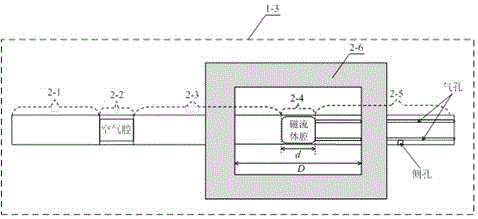
[0052] The structure of the sensor head is as figure 2 shown. Both ends of the rectangular fiber holder are respectively fixed on the second single-mode fiber and the panda fiber, and both fixed ends are at a certain distance from the second hollow-core fiber.

[0053]The thermo-optic coefficient of ferrofluid is two orders of magnitude higher than that of quartz. Therefore, the magnetic field sensor based on ferrofluid cavity must consider the interference of temperature. This patent designs an optical fiber support structure, which uses the thermal expansion effect of the optical fiber support to offset the thermo-optical effect of the magnetic fluid. The principle of temperature compensation is analyzed as follows:

[0054] The change of the optical ...

application example 3

[0067] An application example for making a sensing head of the temperature-insensitive magnetic field sensor 100 based on ferrofluid-filled fiber microcavity of the present invention is described below.

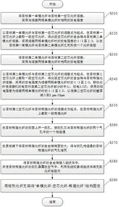
[0068] First, splice common single-mode fiber (as an example of the target first single-mode fiber) with a hollow-core fiber (as an example of the target first hollow-core fiber), and the arc intensity used for fusion splicing is the same as that of splicing two common single-mode fibers under normal conditions. The strength of the fiber is the same.

[0069] Then, starting from the fusion point of ordinary single-mode fiber and hollow-core fiber, cut a section of hollow-core fiber with a length between 50 μm and 200 μm on the hollow-core fiber, and connect the free end of this section of hollow-core fiber to the ordinary single-mode fiber (Example as target second single-mode fiber) splicing. Starting from the fusion splicing point between the hollow core fiber and the ordi...


PUM


Abstract

The invention provides a temperature-insensitive magnetic field sensor based on a magnetic fluid filling optical fiber microcavity. The magnetic field sensor comprises a sensing head, an optical fiber coupler, a spectrograph and a wide-spectrum optical source. The sensing head is formed by an air chamber and a magnetic liquid cavity which are cascaded. An absolute value of a difference between free spectrum scopes of the air chamber and the magnetic liquid cavity is less than 1 / 10 of the magnetic liquid cavity. Wide spectrum light emitted by the wide-spectrum optical source enters into the sensing head via the optical fiber coupler. An optical signal reflected by the air chamber and the magnetic liquid cavity enters into the spectrograph via the optical fiber coupler. An optical signal reflected by the air chamber and the magnetic liquid cavity generates a vernier effect so that measured sensitivity of a magnetic field is greatly increased. An optical fiber support structure designed in the invention is fixed to a single-mode fiber and a panda fiber of two sides of the magnetic liquid cavity, and a thermal expansion effect of an optical fiber support is used to offset a thermo-optic effect of a magnetic fluid so that automatic compensation of a temperature is realized. The magnetic field sensor possesses advantages that the temperature can be automatically compensated; the structure is compact; sensitivity is high; and a measured range is large.

Description

technical field [0001] This patent relates to an optical magnetic field sensor, and specifically designs a temperature-insensitive magnetic field sensor in which a magnetic fluid fills an optical fiber microcavity. Background technique [0002] The optical fiber magnetic field sensor has many advantages such as good safety performance, anti-electromagnetic interference, non-contact measurement, real-time telemetry on site and wide dynamic measurement range. In the field of magnetic field measurement and analysis, fiber optic magnetic field sensors have attracted many scholars to conduct research, and will be widely used in the power detection industry. [0003] Magnetic fluid is a kind of superparamagnetic liquid functional material produced in response to the development of modern science. It has almost no hysteresis phenomenon of solid magnetic substances. Its refractive index changes linearly with the external magnetic field within a certain range, and it is easy to combi...

Claims


Application Information

Patent Timeline
Patent Type & Authority Applications(China)
IPC IPC(8): G01R33/032
CPCG01R33/032
Inventor 杨玉强葛伟杨群
Owner HARBIN UNIV OF SCI & TECH
Learn More