Low-energy-consumption intensifying-denitrifying integrated reactor

An integrated reactor technology, applied in chemical instruments and methods, energy wastewater treatment, water/sludge/sewage treatment, etc., can solve the problems of high nitrogen and phosphorus removal efficiency, low operating costs, etc., to save investment costs , small footprint, strong applicability

Pending Publication Date: 2017-01-25
SCI RES ACADEMY OF GUANGXI ENVIRONMENTAL PROTECTION
11 Cites 0 Cited by

AI-Extracted Technical Summary

Problems solved by technology

[0005] The purpose of the present invention is to provide an integrated reactor for enhanced denitrification with low energy consumption, so as to overcome the shortcomings that the exi...

Method used

Because the aerobic zone 32 of biochemical reaction tank 3 and the top and the bottom of anoxic zone 31 communicate simultaneously, thereby in the process that aerobic zone 32 is aerated, the water body in aerobic zone 32 crosses the first block The upper end of the plate 33 enters the anoxic zone 31, and the water body in the anoxic zone 31 enters the aerobic zone 32 from the lower end of the first baffle plate 33, so as to realize the hydraulic circulation between the aerobic zone 32 and the anoxic zone 31 . The present invention uses the principle of air lift to realize the non-powered internal circulation of the aerobic zone 32 and the anoxic zone 31, and it can reduce the aeration amount of the aerobic zone 32, realize synchronous nitrification and denitrification, reduce energy consumption, and improve denitrification and denitrification. Phosphorus efficiency. Continuing to refer to Fig. 1, preferably, all be provided with stirring device 38 in the anoxic zone 31 of each stage reaction unit, to strengthen hydraulic mixing, thereby guarantee the concentration of dissolved oxygen in the anoxic zone 31 by air-lift circulation and agitation, with Further ensure the efficiency of nitrogen and phosphorus removal. Dissolved oxygen online monitoring instruments can be installed in each anoxic zone 31 to automatically adjust the aeration rate by monitoring dissolved oxygen, thereby saving energy consumption. Moreover, the present invention can be equipped with one-stage or multi-stage reaction units to be suitable for different scales of sewage treatment, and has strong applicability. When multi-stage reaction units are used, the impact load resistance is strong, and the removal of nitrogen and phosphorus can be strengthened. , The effluent water quality is good. In addition, each core reactor can be buried underground, which occupies a small area to save investment costs, and is hygienic and beautiful.
Continue to refer to Fig. 1, when being provided with at least two-stage reaction unit in biochemical reaction tank 3, the anoxic zone 31 of every stage reaction unit is respectively conveyed sewage by a sewage pipe 22, and the deficiency of previous stage reaction unit The water intake of the oxygen zone 31 is greater than the water intake of the anoxic zone 31 of the subsequent reaction unit, so as to reduce the water intake step by step. For example, when two-stage reaction units are provided, the water inflow of the anoxic zone 31 of the first-stage r...

Abstract

The invention discloses a low-energy-consumption intensifying-denitrifying integrated reactor. The integrated reactor comprises a filter tank, a regulating tank, a biochemical reaction tank and a settling tank, wherein at least one stage of reaction unit is arranged in the biochemical reaction tank; each stage of the reaction unit comprises an anoxic region, an aerobic region, an aeration pipe and an aeration system, the top and bottom of the aerobic region are communicated with the top and bottom of the anoxic region so as to realize hydraulic circulation between the aerobic region and the anoxic region, the aeration pipe is arranged at the bottom of the aerobic region, the aeration system is used for supplying oxygen-containing gas to the aeration pipe, and sewage is nitrified in the aerobic region and is denitrified in the anoxic region. According to the low-energy-consumption intensifying-denitrifying integrated reactor, by virtue of the hydraulic circulation between the aerobic region and the anoxic region, the nitrogen and phosphorus removal efficiencies are improved; during the operation of the process, the occupied area is small, the applicability is strong, the monitoring is convenient, and the operation cost is low.

Application Domain

Water contaminantsTreatment involving filtration +5

Technology Topic

Small footprintSewage +6

Image

  • Low-energy-consumption intensifying-denitrifying integrated reactor

Examples

  • Experimental program(1)

Example Embodiment

[0024] The specific embodiments of the present invention will be described in detail below with reference to the accompanying drawings, but it should be understood that the protection scope of the present invention is not limited by the specific embodiments.
[0025] Unless expressly stated otherwise, throughout the specification and claims, the term "comprising" or its conjugations such as "comprising" or "comprising" and the like will be understood to include the stated elements or components, and Other elements or other components are not excluded.
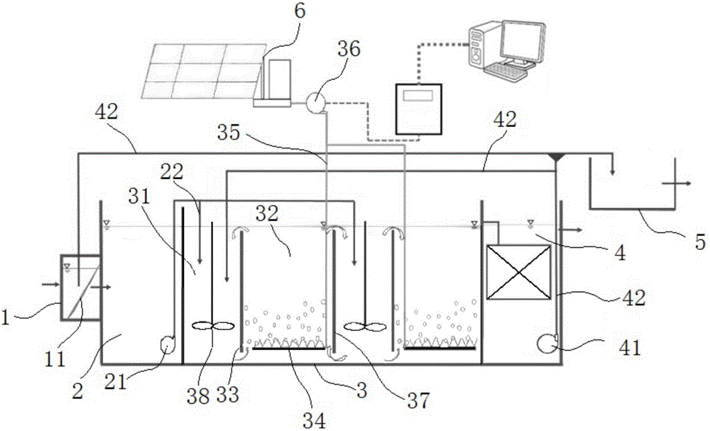
[0026] figure 1 Shown is a schematic structural diagram of a low energy consumption enhanced denitrification integrated reactor according to a preferred embodiment of the present invention, the low energy consumption enhanced denitrification integrated reactor includes a filter tank 1, a regulating tank 2, a biochemical reaction tank 3 and a sedimentation tank 4. The connection sequence of each pool is consistent with the conventional reactor. refer to figure 1 , the interior of the filter tank 1 can be divided into a water inlet cavity and a water outlet cavity by a filter screen 11, the rural domestic sewage is directly discharged into the water inlet cavity, and the sewage enters the water outlet cavity after preliminary filtering by the filter screen 11, Some floating objects and large suspended particles remain in the water inlet cavity, and the filter screen 11 needs to be cleaned regularly during the working process. The filter screen 11 can be a grid net, which is arranged obliquely, so that the filter tank 1 is divided into two upper and lower triangular tank cavities, the upper tank cavity is the water inlet cavity, and the lower pool cavity is the water outlet cavity. . The adjustment tank 2 is connected with the water outlet cavity of the filter tank 1. The domestic sewage in the filter tank 1 enters the adjustment tank 2 through the water outlet cavity. The adjustment tank 2 is the same as the conventional sewage treatment adjustment tank. Preliminary sedimentation and separation of sewage to adjust water quality and water speed, so that the water quality can be balanced, which is conducive to the next process. The sewage in the adjustment tank 2 is pumped to the biochemical reaction tank 3 by the water pump 21, the sewage treated by the biochemical reaction tank 3 is discharged to the sedimentation tank 4 for sedimentation, and finally the treated water is discharged from the sedimentation tank 4. 4 can be provided with a liquid level gauge to timely control the drainage of the sedimentation tank 4 to the outside. Preferably, the sedimentation tank 4 is an inclined tube sedimentation tank.
[0027] continue to refer to figure 1 , the interior of the biochemical reaction pool 3 of the present invention is provided with at least one-stage reaction units, and each stage of the reaction unit includes an anoxic zone 31, an aerobic zone 32, an aeration pipe 34 and an aeration system, and the sewage is transported from the adjustment pool 2 to the deficient zone 31. In the oxygen-deficient zone 31 , the anoxic zone 31 is the same as the anoxic zone of the conventional biochemical reaction tank, and sludge is stored in the anoxic zone 31 for denitrification and phosphorus removal of sewage by the activated sludge method. Preferably, a mud pump 41 is provided in the sedimentation tank 4, and the anoxic zones 31 of each stage of the reaction unit are connected to the mud pump 41 through a sludge pipeline 42 provided with a valve, so as to replenish sludge to each anoxic zone 31 in time . In addition, the mud pump 41 is also connected to a sludge dewatering tank 5 through a sludge pipeline provided with a valve, so that the sludge in the sedimentation tank 4 can be discharged into the sludge dewatering tank 5 through the mud pump 41. The dewatered sludge in the sludge dewatering tank 5 is regularly transported out for cleaning.
[0028] continue to refer to figure 1 , the top of the aerobic zone 32 is communicated with the top of the anoxic zone 31, and the bottom of the aerobic zone 32 is communicated with the bottom of the anoxic zone 31, so that the aerobic zone 32 and the Hydraulic circulation can be performed between the anoxic zones 31 . The aerobic zone 32 and the anoxic zone 31 of each stage of the reaction unit can be separated by a first baffle 33, the upper end of the first baffle 33 is lower than the top of the biochemical reaction tank 3, and the lower end of the first baffle 33 It is higher than the bottom of the biochemical reaction tank 3 , so that the aerobic zone 32 communicates with the top and bottom of the anoxic zone 31 . The aeration pipe 34 is arranged at the bottom of the aerobic zone 32 and is higher than the lower end of the first baffle 33 to prevent the gas from the aeration pipe 34 from entering the anoxic zone 31 from the bottom. The aeration system is used to provide oxygen-containing gas to the aeration pipe 34 and drive the water body in the aerobic zone 32 to rise upward, and the oxygen-containing gas can directly use air.
[0029] Since the top and bottom of the aerobic zone 32 and the anoxic zone 31 of the biochemical reaction tank 3 communicate with each other at the same time, in the process of aerating the aerobic zone 32, the water in the aerobic zone 32 passes over the first baffle plate 33. The upper end enters the anoxic zone 31 , and the water in the anoxic zone 31 enters the aerobic zone 32 from the lower end of the first baffle 33 to realize hydraulic circulation between the aerobic zone 32 and the anoxic zone 31 . The present invention utilizes the principle of air lift to realize the unpowered internal circulation of the aerobic zone 32 and the anoxic zone 31, and can reduce the aeration amount of the aerobic zone 32, realize simultaneous nitrification and denitrification, so as to reduce energy consumption and improve denitrification and removal. Phosphorus Efficiency. continue to refer to figure 1, preferably, a stirring device 38 is provided in the anoxic zone 31 of each stage of the reaction unit to strengthen hydraulic mixing, so as to ensure the concentration of dissolved oxygen in the anoxic zone 31 through air lift circulation and stirring to further ensure denitrification. Efficiency of Phosphorus Removal. Each anoxic zone 31 may be provided with a dissolved oxygen online monitoring instrument, so as to automatically adjust the aeration amount by monitoring the dissolved oxygen, thereby saving energy consumption. Moreover, the present invention can be provided with one-stage or multi-stage reaction units to be suitable for different scales of sewage treatment, and its applicability is strong. When multi-stage reaction units are used, its anti-shock load capability is strong, and the removal of nitrogen and phosphorus can be strengthened. , the water quality is good. In addition, each core reactor can be buried in the ground, and the floor area is small, so that investment costs can be saved, and it is hygienic and beautiful.
[0030] continue to refer to figure 1 , when the biochemical reaction pool 3 is provided with at least two-stage reaction units, the aerobic zone 32 of the former reaction unit is adjacent to the anoxic zone 31 of the latter reaction unit, and the aerobic zone 32 of the former reaction unit is adjacent to The top of the oxygen-deficient zone 31 of the next-stage reaction unit communicates with the top of the oxygen-deficient zone 31 of the next-stage reaction unit, and the bottom of the aerobic zone 32 of the previous-stage reaction unit is communicated with the bottom of the oxygen-deficient zone 31 of the next-stage reaction unit, so that the phase Adjacent two-stage reaction units are capable of hydraulic circulation. The aerobic zone 32 of the former reaction unit and the anoxic zone 31 of the latter reaction unit can be separated by a second baffle 37, and the upper end of the second baffle 37 is lower than the top of the biochemical reaction tank 3, And the lower end of the second baffle 37 is higher than the bottom of the biochemical reaction tank 3, so that the multi-stage reaction units can be combined together, and the water in the aerobic zone 32 of the previous reaction unit can be released from the upper end of the second baffle 37. Enter the anoxic zone 31 of the next-stage reaction unit, and the water in the anoxic zone 31 of the next-stage can also enter the aerobic zone 32 of the previous-stage reaction unit from the lower end of the second baffle 37 to achieve phase The hydraulic circulation between adjacent reaction units further improves the effect of sewage treatment.
[0031] continue to refer to figure 1 , when the biochemical reaction tank 3 is provided with at least two-stage reaction units, the anoxic zones 31 of each stage of the reaction units transport sewage separately through a sewage pipe 22, and the water intake of the anoxic zones 31 of the previous reaction units is greater than The water inflow of the oxygen-deficient zone 31 of the latter-stage reaction unit can be reduced step by step. For example, when two-stage reaction units are provided, the water inflow rate between the oxygen-deficient zone 31 of the previous-stage reaction unit and the oxygen-deficient zone 31 of the latter-stage reaction unit can be designed to be 2:1. The aeration amount of the aerobic zone 32 of the previous reaction unit is greater than that of the aerobic zone 32 of the subsequent reaction unit, so that the dissolved oxygen in the aerobic zone 32 of the reaction unit is gradually increased. Preferably, the dissolved oxygen in the aerobic zone 32 of the first-stage reaction unit is 0.5-1 mg/L, and the dissolved oxygen in the aerobic zone 32 of the last-stage reaction unit is 1.5-2.0 mg/L. The amount of aeration in zone 32 enables efficient hydraulic circulation of the liquids in the different stages of reaction units. When the multi-stage reaction unit is set in the present invention, the nitrogen and phosphorus removal effect of the process can be strengthened by adjusting the grading water inflow amount and the aeration amount.
[0032] continue to refer to figure 1 , further preferably, a water pump 21 is provided in the regulating tank 2, the sewage pipes 22 of the anoxic zone 31 of each stage of the reaction unit are connected with the water pump 21, and the sewage pipes 22 of the anoxic zone 31 of each stage of the reaction unit are provided with a The liquid flow meter can transport the sewage in the conditioning tank 2 to the oxygen-deficient area 31 of each stage of the reaction unit through the water pump 21, so as to accurately control the water intake of the oxygen-deficient area 31 of each stage of the reaction unit.
[0033] continue to refer to figure 1 , Further preferably, the aeration system includes an air pump 36, an air pipe 35 and a control system, the air pump 36 is used for pumping air, the aeration pipe 34 is connected with the air pump 36 through the air pipe 35, and a gas flow meter is provided on the air pipe 35; all The aeration pipes 34 of the reaction unit may share an air pump 36 . The control system is used to control the air pump to work in 36 rows. The control system includes PLC control and computer remote monitoring system, so that the present invention can perform remote control through automatic monitoring, which is convenient for long-term supervision of sewage treatment facilities. The present invention can also be provided with a solar energy system 6, and the solar energy system 6 converts the solar energy into the electric energy required by the aeration system, so as to reduce the energy consumption and save the cost.

PUM

no PUM

Description & Claims & Application Information

We can also present the details of the Description, Claims and Application information to help users get a comprehensive understanding of the technical details of the patent, such as background art, summary of invention, brief description of drawings, description of embodiments, and other original content. On the other hand, users can also determine the specific scope of protection of the technology through the list of claims; as well as understand the changes in the life cycle of the technology with the presentation of the patent timeline. Login to view more.

Similar technology patents

Yacht monitoring device and system

InactiveCN102156428AReduce monitoring costsStrong applicability
Owner:DALIAN JIAOTONG UNIVERSITY

Indoor personnel evacuation simulation method based on hybrid space

InactiveCN106897541AStrong applicabilityImprove simulation accuracy
Owner:HUAZHONG NORMAL UNIV

Classification and recommendation of technical efficacy words

  • Improve nitrogen and phosphorus removal efficiency
  • Strong applicability

Method for enhancing sewage nitrogen and phosphorus removal and saving energy and reducing consumption based on pulse aeration

ActiveCN104944701AImprove nitrogen and phosphorus removal efficiencyReduce operating energy consumption
Owner:KUNMING DIANCHI WATER TREATMENT CO LTD

Multipoint water-in sludge in-situ reduction synchronous coupling nitrogen and phosphorus removal method

InactiveCN106630144AImprove nitrogen and phosphorus removal efficiencyLess investment in infrastructure
Owner:HEBEI UNIV OF ENG
Why Eureka
Try Eureka