
Minimally-invasive intracranial pressure and intracranial temperature monitoring system and probe zeroing method

A monitoring system and internal temperature technology, applied in the field of medical devices, can solve the problems of affecting signal stability, cumbersome use process, low yield, etc., to achieve high measurement accuracy and stability, improve production efficiency and improve design solutions. Effect

Pending Publication Date: 2017-02-01
JIANGSU AISIPU MEDICAL TECH CO LTD
View PDF6 Cites 5 Cited by
  • Summary
  • Abstract
  • Description
  • Claims
  • Application Information

AI Technical Summary

Problems solved by technology

However, due to the design of the probe structure, the manufacturing process is complicated, the yield is very low, and the product cost cannot be controlled, so that the patient cannot bear the treatment cost of using the probe, and it cannot be promoted in the clinical field.
Second, because the structural design consistency of the sensor and the probe cannot meet the clinical measurement accuracy, it is necessary to use the host to correct the probe when using it, and it is impossible to freely replace the new probe, and the use process is more cumbersome
Third, the existing system does not include wireless relay station equipment, cannot form a multi-level multi-user network, and the transmission distance is relatively short, which cannot meet the needs of complete monitoring
Fourth, because the electrical signal given by the sensor is extremely small, it will be interfered when it is transmitted to the host as an analog signal through a wire, which will affect the stability of the signal

Method used


Image

  • Minimally-invasive intracranial pressure and intracranial temperature monitoring system and probe zeroing method
  • Minimally-invasive intracranial pressure and intracranial temperature monitoring system and probe zeroing method
  • Minimally-invasive intracranial pressure and intracranial temperature monitoring system and probe zeroing method

Examples


Embodiment 1

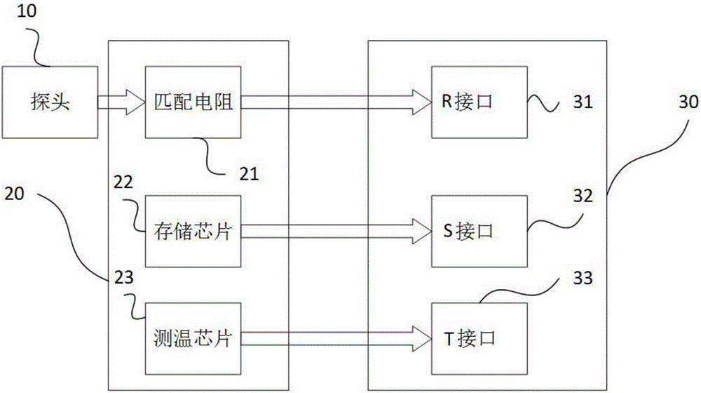
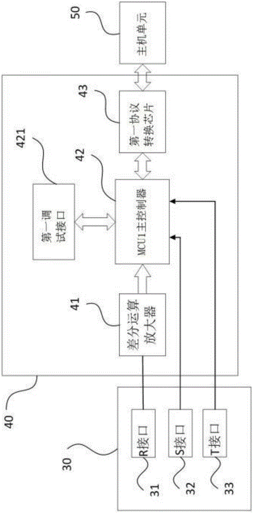
[0038] like Figure 1-6 A minimally invasive intracranial pressure and intracranial temperature monitoring system shown includes a probe 10, a zeroing module 20, an interface module 30, an amplifying AD module 40, a host unit 50 and a wireless repeater 60, and the probe 10 is connected to zeroing Module 20, the zeroing module 20 is connected to the interface module 30, the interface module 30 is connected to the amplifying AD module 40, the amplifying AD module 40 is connected to the host unit 50, and the host unit 50 is connected to the wireless repeater 60 through a 2.4G wireless communication network;

[0039] The zeroing module 20 includes a temperature measuring chip 23, a memory chip 22 and a bridge matching resistor 21, and the probe 10 is connected to the bridge matching resistor 21;

[0040] The interface module 30 includes a T interface 33, an S interface 32 and an R interface 31, the bridge matching resistor 21 is connected to the R interface 31, the memory chip 22 ...

Embodiment 2

[0049] like Figure 1-7 The difference between the minimally invasive intracranial pressure and intracranial temperature monitoring system shown in Embodiment 1 is that it also includes a drainage tube 10B0, one end of the drainage tube 10B0 is closed by a plug 10B2 to form a closed end, and the other end is a At the open end, the drainage tube 10B0 is provided with a probe cavity 10B1, a guide needle cavity 10B3 and a drainage cavity 10B4, and the end of the drainage cavity 10B4 protruding from the opening end of the drainage tube 10B0 is provided with an adapter 10B6, and the probe cavity The probe 10 is placed in 10B1, and an opening is set in the shell of the probe cavity 10B1 corresponding to the probe 10. The pressure sensor 13 extends out of the drainage tube 10B0 from the opening and is used to contact the brain tissue to obtain pressure. The guide needle cavity 10B3 is placed in the guide Needle.

Embodiment 3

[0051] A probe zeroing method of a minimally invasive intracranial pressure and intracranial temperature monitoring system is realized on the basis of a minimally invasive intracranial pressure and intracranial temperature monitoring system described in Embodiment 1 or Embodiment 2, It includes the following steps:

[0052] Step 1: Establish the test environment: first install the probe 10 on the pressure gauge, apply a fixed pressure value to the probe 10 through the pressure gauge, then adjust the ambient temperature of the probe 10 to 25 degrees room temperature; finally adjust the bridge matching resistance 21. The bridge matching resistor 21 sends the pressure signal collected by the probe 10 to the MCU1 main controller 42, and the MCU1 main controller 42 uses the pressure signal collected by the probe 10 in the test environment as the parameter of the probe 10, and Write the parameters of the probe 10 into the memory chip 22;

[0053] Step 2: Put the probe 10 into the p...


PUM


Abstract

The invention discloses a minimally-invasive intracranial pressure and intracranial temperature monitoring system and a probe zeroing method and belongs to the technical field of medical devices. The minimally-invasive intracranial pressure and intracranial temperature monitoring system comprises a probe (10), a zeroing module (20), an interface module (30), an amplifying AD module (40), a host unit (50) and a wireless repeater (60); the effect of continuously monitoring the change in the intracranial pressure and the intracranial temperature of a patient in real is realized, and the transmission of intracranial pressure and intracranial temperature parameters can be performed through the repeater by means of a wireless network.

Description

technical field [0001] The invention belongs to the technical field of medical equipment. Background technique [0002] Due to traffic accidents, falls, impacts and other external forces, the number of traumatic brain injury patients is increasing year by year. At the same time, there are more and more neurosurgery patients due to internal diseases and tumors. Due to its high risk, neurosurgery requires strict postoperative observation of patients. The most convenient and effective observation method is to continuously monitor the patient's intracranial pressure and intracranial temperature. If the intracranial pressure continues to rise, it will cause a series of complications and eventually lead to the death of the patient. Therefore, doctors or nurses need to know the patient's intracranial pressure in real time, and take reasonable and effective drug treatment or drainage treatment plan according to the specific value of intracranial pressure. Intracranial temperatur...

Claims


Application Information

Patent Timeline
Patent Type & Authority Applications(China)
IPC IPC(8): A61B5/03A61B5/02
CPCA61B5/02A61B5/031
Inventor 黄若冰钱志余王淑瑾金晓曦付蒙金美玉吴华炜姚敏
Owner JIANGSU AISIPU MEDICAL TECH CO LTD
Learn More