Camshaft machining process and forging die

A processing technology and camshaft technology, applied in the field of camshaft processing technology and forging dies for processing camshafts, can solve the problems of low material utilization rate, low production efficiency, insufficient filling of camshaft eccentric wheel B, etc.

Active Publication Date: 2017-02-01
湖南高致精工机械有限公司
View PDF6 Cites 4 Cited by
  • Summary
  • Abstract
  • Description
  • Claims
  • Application Information

AI Technical Summary

Problems solved by technology

The blank selected in this way can well form the camshaft and the uniform flash, but the size is large, and the two ends need to be drawn out during production, so the production efficiency is lo...

Method used


Image

  • Camshaft machining process and forging die
  • Camshaft machining process and forging die
  • Camshaft machining process and forging die

Examples


Embodiment 1

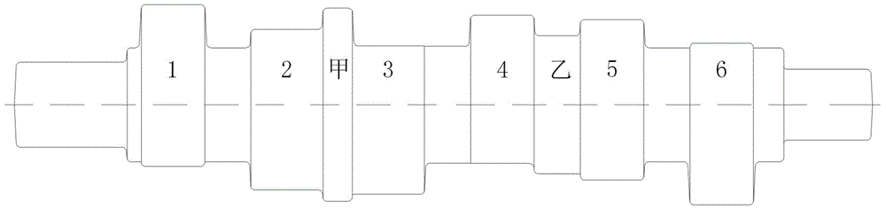
[0022] A camshaft machining process, the camshaft includes a cam, an eccentric wheel, a central shaft diameter and cylinders at both ends, the process adopts the following process steps:

[0023] A, moulding, make the mold that has cavity and flash groove, the shape of described cavity is identical with the external shape of camshaft forging, and described flash groove only has flash bridge portion;

[0024] B. Material selection. The specifications of the selected blank are determined according to the following two points:

[0025] 1) The cross-sectional area of ​​the selected blank is larger than the cross-sectional area of ​​the shaft diameter part in the middle of the camshaft, and smaller than the cross-sectional area of ​​the cam part of the camshaft;

[0026] 2) There should be enough clearance between the outer peripheral surface of the selected billet and the widest part of the mold cavity to ensure that the billet can generate a large axial flow along the length dire...

Embodiment 2

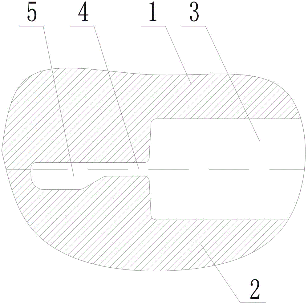
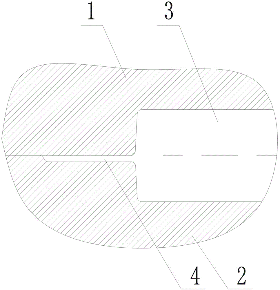
[0029] Such as image 3 A forging die for machining camshafts is shown, including an upper die 1 and a lower die 2 that match each other, the corresponding surface between the upper die 1 and the lower die 2 is a parting surface, and the upper die is provided with a lower die cavity , the lower mold is provided with a lower mold cavity, and the lower mold cavity and the lower mold cavity are symmetrically arranged to form a cavity 3. The shape of the cavity 3 is the same as the external shape of the camshaft forging, and a flash groove is arranged around the cavity 3 , the flash slot only has a flash bridge portion 4 .

[0030] Because the flash groove in the technical solution only has the flash bridge part 4, the flash bin part in the traditional flash structure is cancelled, so the resistance to the radial flow of the metal blank can be increased, and the metal blank can be pushed along the length. The axial flow is carried out in the direction, so that the blank correspon...


PUM

PropertyMeasurementUnit
Heightaaaaaaaaaa
Widthaaaaaaaaaa

Abstract

The invention provides a camshaft machining process. The camshaft machining process includes the following steps: A, mold making, wherein a mold having a mold cavity and a flash groove is made, the shape of the mold cavity is same as the exterior shape of a camshaft forging, and the flash groove only has a flash bridge portion; B, the choice of materials, wherein the specification of a selected billet material is determined according to the following two points: 1) the cross-sectional area of the billet material is greater than that of a central shaft portion of a camshaft and less than that of a cam portion of the camshaft; 2) sufficient clearance should be formed between the outer circumference surface of the billet material and the widest portion of the mold cavity, so as to ensure that the billet material has a larger axial flow in a length direction when forged. The invention further provides a forging die for camshaft machining. The forging die comprises an upper die, a lower die and a die cavity, flash groove is formed in the periphery of the die cavity and only has a flash bridge portion; by adopting the technical proposal, the production efficiency and the material utilization rate can be improved, and the product quality can be ensured.

Description

technical field [0001] The invention relates to the field of forging, in particular to a camshaft machining process and a forging die used for machining the camshaft. Background technique [0002] Such as figure 1 A camshaft part is shown, which is composed of cam 1, cam 2, cam 3, cam 4, cam 5, cam 6, eccentric wheel A, eccentric wheel B, middle shaft diameter and cylinders at both ends, belonging to the long axis Class forgings, in which the cross-sectional area of ​​the cam and eccentric wheel is large, and the cross-sectional area of ​​the shaft diameter is small. Such camshafts are usually used as figure 2 The shown forging die is forged. The forging die includes an upper die 1 and a lower die 2. A cavity 3 is provided on the joint surface of the upper die 1 and the lower die 2. A flash structure is provided around the die cavity 3. The flash The edge structure is composed of a flash bridge part 4 and a flash bin part 5 . Before the camshaft blank is forged, it is n...

Claims


Application Information

Patent Timeline
IPC IPC(8): B21K1/06B21J13/02
CPCB21J13/02B21K1/06
Inventor 刘钧沈运海沈祁阳蒲焕章
Owner 湖南高致精工机械有限公司
Why Eureka
Try Eureka