
Mechanism capable of improving parallel light ejection of LED exposure machine

A technology of parallel light and exposure machine, which is applied in the field of etching, circuit board exposure, and development, and can solve the problems that affect the processing accuracy of PCB board 5 and cannot reach the processing accuracy.

Inactive Publication Date: 2017-02-01
DONGGUAN BEIKE ELECTRONICS TECH CO LTD
View PDF6 Cites 1 Cited by
  • Summary
  • Abstract
  • Description
  • Claims
  • Application Information

AI Technical Summary

Problems solved by technology

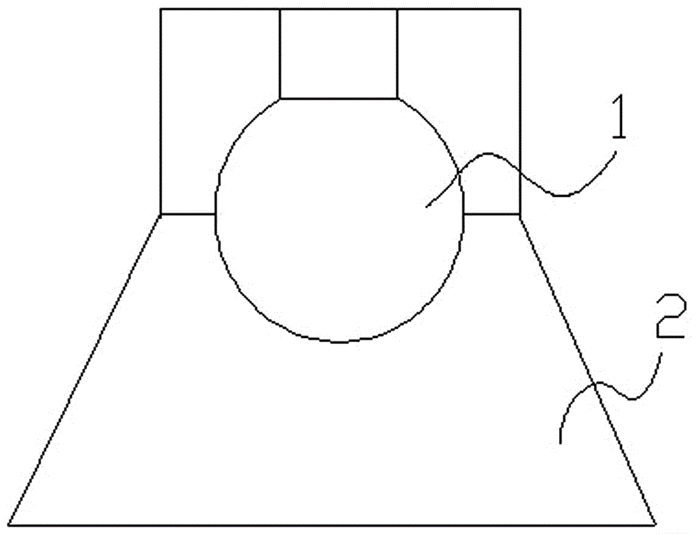
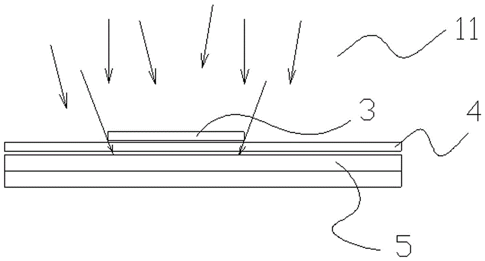
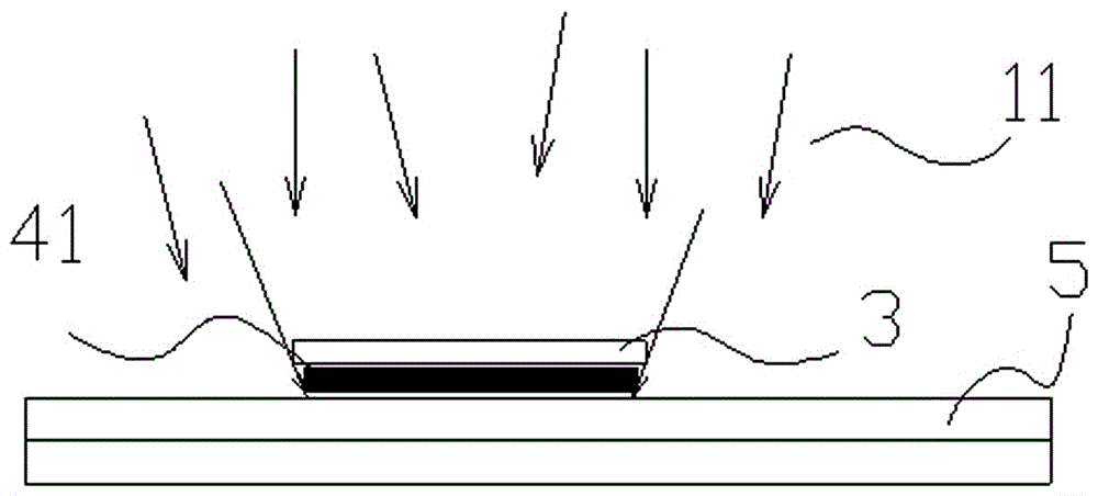
[0003] Since the light 11 is scattered by the reflective cup 2, the light scattered from the light source 1 is constrained into parallel light by the principle of light reflection, as shown in the attached Figure 1~3 As shown, when the light source is set in the reflector 2, to ensure that the light scattered by the light source 1 is constrained into parallel light rays 11, the light source 1 must be set at the focus of the reflector 2, due to the processing accuracy of the reflector 2 And the objective problem of the assembly accuracy of the light source 1 exists. The light 11 scattered by the light source 1 is difficult to be constrained into parallel light 11, so that the dry / wet film 4 between the PCB board 5 and the film 3 is subjected to non-parallel Due to the influence of light 11, the processed dry / wet film 41 cannot reach the processing accuracy in the illumination range of non-parallel light 11, which in turn affects the processing accuracy of the entire PCB board 5

Method used


Image

  • Mechanism capable of improving parallel light ejection of LED exposure machine
  • Mechanism capable of improving parallel light ejection of LED exposure machine
  • Mechanism capable of improving parallel light ejection of LED exposure machine

Examples


Embodiment Construction

[0020] See attached Figure 4~7 , an improved parallel light emission mechanism of an LED exposure machine, comprising a PCB board 5, a light source 1 and a reflective cup 2, the reflective cup 2 is fixed on the PCB board 5, and the light source 1 is fixed on the PCB board 5 at the inner focus position of the reflective cup 2, A light guide cover 7 is also included, and the light guide cover 7 is fixed on the open end of the reflective cup 2 and coaxial with the reflective cup 2 .

[0021] The light guide cover 7 is coated with a light-absorbing material.

[0022] The light guide cover 7 is preferably made of aluminum.

[0023] The light guide cover 7 is made of high temperature resistant plastic material.

[0024] The light guide cover 7 is made of glass material.

[0025] When the present invention is used, the light source 1 generates light after it is energized. Due to the objective problems of the processing accuracy of the reflective cup 2 and the assembly accuracy of...


PUM


Abstract

The invention relates to the technical field of circuit board exposure, development and etching, in particular to a mechanism capable of improving parallel light ejection of an LED exposure machine in an exposure process. The mechanism is achieved through the technical scheme as follows: the mechanism capable of improving parallel light ejection of the LED exposure machine comprises a PCB, a light source, a reflection cup and a light guide cover, wherein the reflection cup is fixed on the PCB; the light source is fixed on the PCB at a focus position in the reflection cup; and the light guide cover is fixed at an open end of the reflection cup and the light guide cover and the reflection cup are in the same axis. The light guide cover is added to a travel road of the light source for emitting light, so that a plurality of unparallel light rays are restrained in the light guide cover in the working process and are changed into parallel light rays through a light-absorbing material on the light guide cover; the parallel light rays are exposed, developed and etched after being irradiated to obtain a line which is equal to a film in width; and the working accuracy of the overall PCB is ensured.

Description

technical field [0001] The invention relates to the technical fields of exposure, development and etching of circuit boards, in particular to a parallel light emitting mechanism capable of improving the exposure process of an exposure machine. Background technique [0002] LED exposure machine is a complex semiconductor processing equipment integrating electrical, mechanical, vacuum and computer technology. The basic working principle of LED exposure machine is to use focused electron beam to expose organic polymer (commonly known as electronic resist or photoresist) under the control of computer. The photoresist after being irradiated by electron beam has a physical The chemical properties change, and a well-dissolved or non-dissolved area is formed in a certain solvent, thereby forming a fine pattern on the resist. [0003] Since the light 11 is scattered by the reflective cup 2, the light scattered from the light source 1 is constrained into parallel light by the princip...

Claims


Application Information

Patent Timeline
IPC IPC(8): G03F7/20
CPCG03F7/70091G03F7/70008G03F7/7015
Inventor 徐晓华徐忠良吴雄
Owner DONGGUAN BEIKE ELECTRONICS TECH CO LTD
Learn More