S-shaped piezoelectric cantilever beam vibration energy collector

A vibration energy harvesting, cantilever beam technology, applied in piezoelectric effect/electrostrictive or magnetostrictive motors, generators/motors, electrical components, etc. The miniaturization of the device and the reduction of the collected energy can achieve the effects of low processing cost, improved energy conversion efficiency, and improved stability.

Inactive Publication Date: 2017-02-01
ANHUI UNIVERSITY
View PDF1 Cites 14 Cited by
  • Summary
  • Abstract
  • Description
  • Claims
  • Application Information

AI Technical Summary

Problems solved by technology

But there are also disadvantages: if the resonance frequency is lowered, the length of the cantilever must be increased, but too long cantilever is not conducive to the miniaturization of the device
In addition, most of the existing energy harvesters work at a fixed frequency, that is, the energy harvester can only work within a narrow single frequency range, while the vibration source frequency in the environment may

Method used


Image

  • S-shaped piezoelectric cantilever beam vibration energy collector
  • S-shaped piezoelectric cantilever beam vibration energy collector
  • S-shaped piezoelectric cantilever beam vibration energy collector

Examples


Embodiment Construction

[0023] The device of the present invention will be further described in detail below in conjunction with the accompanying drawings.

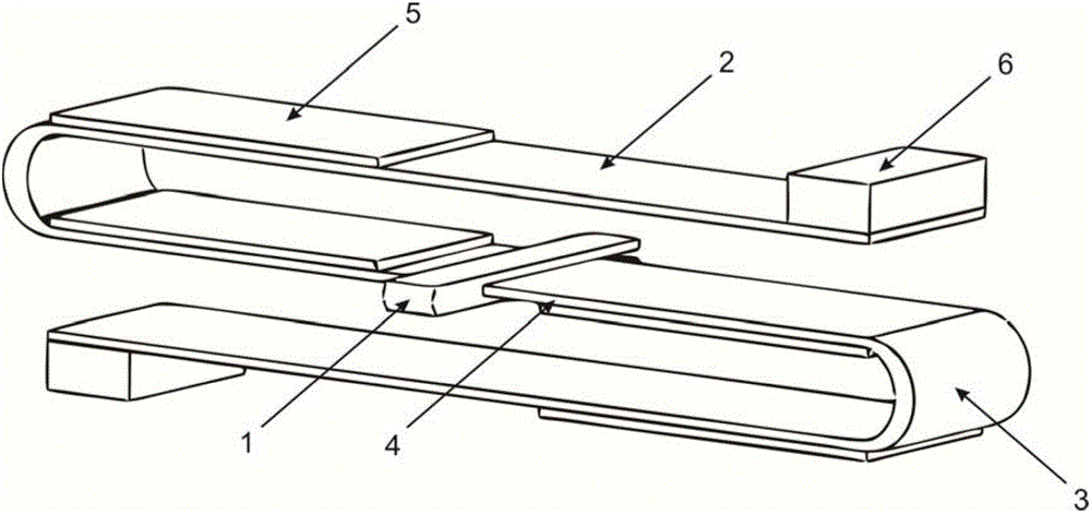
[0024] refer to figure 1 , An S-shaped piezoelectric cantilever beam vibration energy harvester disclosed in the present invention is composed of a support 1 , a free section 2 , a bending section 3 , a substrate section 4 , a piezoelectric element 5 , and a mass block 6 . An S-shaped cantilever beam mounted on the support is fixed on the support 1, and the S-shaped cantilever beam is composed of a substrate section 4, a curved section 3 and a free section 2; the surfaces of the substrate section 4 and the free section 2 are bonded The piezoelectric element 5 is glued; the end of the free section 2 is fixed with a quality block 6 .

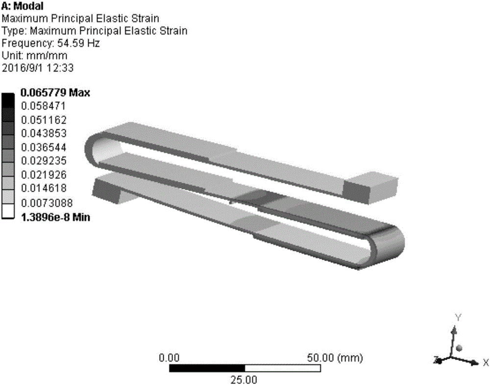
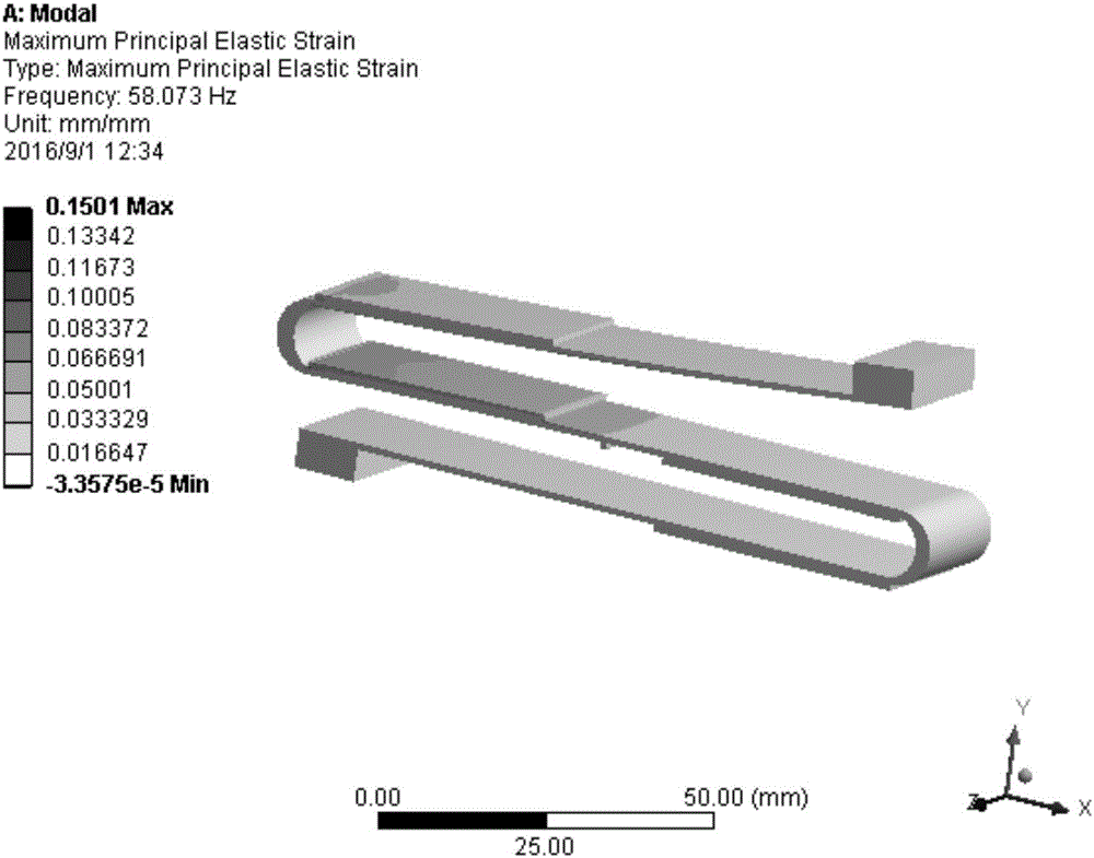
[0025] refer to figure 2 , image 3 , the first-order and second-order modal simulation diagrams are simulated under the environment of ANSYS workbench14.5, and the English in the attached drawings are automatic...


PUM


Abstract

The invention discloses an S-shaped piezoelectric cantilever beam vibration energy collector. The S-shaped piezoelectric cantilever beam vibration energy collector comprises a supporting seat and an S-shaped cantilever beam fixedly mounted on the supporting seat, wherein the S-shaped cantilever beam comprises a substrate section, bent sections and free sections; piezoelectric elements are mounted on the surfaces of the substrate section and the free sections for converting energy generated by the vibration of the cantilever beam into electric energy; mass blocks are mounted at the tail ends of the free sections for adjusting the resonant frequency and vibration amplitude value of the cantilever beam; and the rigidity of the bent sections is far greater than that of the substrate section and the free sections. According to the vibration energy collector provided by the invention, the front two orders of vibration modes of the system are controlled through the S-shaped piezoelectric cantilever beam and the mass blocks at the tail end to form a relatively wide working frequency band; in addition, the apparatus is easy to start oscillation, and high in recycling efficiency and the operating stability; and conversion of the environment vibration energy can be realized.

Description

technical field [0001] The invention relates to the fields of vibration application and electric power technology, in particular to an S-shaped piezoelectric cantilever beam vibration energy harvester, which belongs to the technical field of converting mechanical energy generated in a vibration environment into electrical energy and collecting it for use by microelectronic devices. Background technique [0002] With the continuous advancement of micro-electromechanical processing technology and wireless technology, electronic devices such as embedded systems, wireless sensor networks, smart wearable devices, and various implantable micro-sensors have entered the era of miniaturization, integration, and low power consumption. However, energy supply technology has become a bottleneck restricting the further development of the above-mentioned electronic devices. Traditional chemical batteries have various defects such as large size, limited life, and need to be replaced manuall...

Claims


Application Information

Patent Timeline
IPC IPC(8): H02N2/18
CPCH02N2/188
Inventor 刘永斌赵艺雷李国丽琚斌华飞陆思良刘方
Owner ANHUI UNIVERSITY
Why Eureka
Try Eureka