Automatic cleaning device for contact net insulator

An automatic cleaning and insulator technology, applied in cleaning methods and utensils, cleaning methods using tools, overhead line/cable equipment, etc., can solve problems such as uneven distribution of voltage on the surface of insulators, leakage, etc.

Inactive Publication Date: 2017-02-15
SHIJIAZHUANG TIEDAO UNIV
View PDF5 Cites 5 Cited by
  • Summary
  • Abstract
  • Description
  • Claims
  • Application Information

AI Technical Summary

Problems solved by technology

[0007] Insulators operating online are exposed to the atmosphere for a long time, and are affected by environmental factors such as natural dust and industrial emissions. A layer of dirt is gradually deposited on the surface. In dry weather, these insulators with dirt on the surface are still It can maintain a high insulation level, and its discharge voltage is close to that in a clean and dry state. However, in wet days such as fog, dew, drizzle, and melting ice and snow, the surface of the insulator will form after the surface of the insulator is damp. Water film, the soluble salts in the dirty layer will dissolve in water, thus forming a conductive water film, causing the dirty layer to become a conductive layer after being wet, and under the action of the operating voltage, the surface will generate leakage current and Joule heat , in the local area where the current density is high and the resistance of the dirty layer is high, the dirty layer is dried to form a dry zone. The formation of the dry zone interrupts the leakage current and makes the voltage distribution on the surface of the insulator more uneven. The dry zone bears a higher voltage. When the electric field strength When it is large enough, it will cause the pulse of air breakdown and leakage current on the drying belt. The discharge on the drying belt is connected in series with the resistance of the drying dirt layer. Partial arc, partial arc is an intermittent discharge process. This intermittent discharge state lasts for a long time. When the state of dirt and humidity is serious, the partial arc will gradually develop. When it reaches and exceeds the critical state, the arc will will penetrate both poles, resulting in a flashover

Method used


Image

  • Automatic cleaning device for contact net insulator
  • Automatic cleaning device for contact net insulator
  • Automatic cleaning device for contact net insulator

Examples


Embodiment Construction

[0023] The technical solutions in the embodiments of the present invention are clearly and completely described below in conjunction with the accompanying drawings in the embodiments of the present invention. Obviously, the described embodiments are only part of the embodiments of the present invention, not all of them. Based on the embodiments of the present invention, all other embodiments obtained by persons of ordinary skill in the art without making creative efforts belong to the protection scope of the present invention.

[0024] In the following description, a lot of specific details are set forth in order to fully understand the present invention, but the present invention can also be implemented in other ways different from those described here, and those skilled in the art can do it without departing from the meaning of the present invention. By analogy, the present invention is therefore not limited to the specific examples disclosed below.

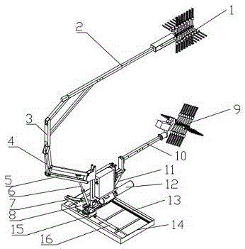
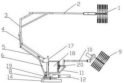
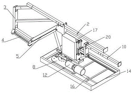
[0025] Such as Figure...


PUM


Abstract

The invention discloses an automatic cleaning device for a contact net insulator. The automatic cleaning device comprises an underframe, a support plate, a linear sliding mechanism, a slewing mechanism, a turnover mechanism and a cleaning mechanism. The underframe is of a rectangular frame structure. The support plate is installed on the inner side of the underframe by means of the linear sliding mechanism. The slewing mechanism is fixedly installed on the upper surface of the support plate. A slewing disc is installed at the action end of the slewing mechanism. The cleaning mechanism is installed on the slewing disc through a support. The turnover mechanism is installed between the support and the slewing disc. The cleaning mechanism is installed on the underframe by means of the slewing mechanism and the linear sliding mechanism, thus automatic cleaning device is in match usage with an existing railway operation vehicle, the surface of the insulator can be cleaned during advancing, an operator does not need to be close to the insulator, the operation safety and operation efficiency are improved, flashover of the insulator is avoided effectively, and normal operation of a contact net is ensured.

Description

technical field [0001] The invention relates to the technical field of catenary maintenance equipment, in particular to an automatic cleaning device for catenary insulators. Background technique [0002] The insulator is an important part that suspends and supports various wires to maintain electrical insulation performance, and to provide sufficient distance and insulation between the live conductor or the conductor and the grounding body. It plays two basic functions in the catenary. That is, support the wire and prevent current from returning to ground. [0003] There are tens of thousands of insulators of various types in the electrified railway catenary. If one of the insulators is damaged by pollution flashover, the insulator damage is equivalent to a two-phase short circuit. The strong short circuit current will cause the feeder of the traction substation to trip, and the terminal Railway power supply, if it is not handled in time, it will constitute a traffic accide...

Claims


Application Information

Patent Timeline
Patent Type & Authority Applications(China)
IPC IPC(8): B08B1/04H02G1/02
CPCB08B1/04H02G1/02
Inventor 吴文江段成华宋修军姜红敏张旭
Owner SHIJIAZHUANG TIEDAO UNIV
Why Eureka
Try Eureka