Grass-cutting hob, cutter welding tool of grass-cutting hob and manufacturing method of grass-cutting hob

A manufacturing method and welding tooling technology, applied in manufacturing tools, welding equipment, welding equipment and other directions, can solve the problems of poor quality and high cost, and achieve the effects of reducing work difficulty, high positioning accuracy and improving welding efficiency

Active Publication Date: 2017-02-15
MAANSHAN GREEN FRIEND MACHINE MFG
View PDF11 Cites 11 Cited by
  • Summary
  • Abstract
  • Description
  • Claims
  • Application Information

AI Technical Summary

Problems solved by technology

[0005] Aiming at the problem of high cost or poor quality of the existing grass cutting hob manufacturing method, the present invention provides a grass cutting hob, which can improve the assembly accuracy before welding after adding positioning holes, and can improve the assembly efficiency by adding multiple positioning holes; A cutterhead welding tool for a grass cutting hob, which is provided with a structure corresponding to the grass cutting hob, improves welding efficiency and welding accuracy; provides a manufacturing method of a grass cutting hob, by combining the improvement of the grass mowing hob and the The original process is adjusted to obtain a higher quality mowing reel without increasing the production cost

Method used


Image

  • Grass-cutting hob, cutter welding tool of grass-cutting hob and manufacturing method of grass-cutting hob
  • Grass-cutting hob, cutter welding tool of grass-cutting hob and manufacturing method of grass-cutting hob
  • Grass-cutting hob, cutter welding tool of grass-cutting hob and manufacturing method of grass-cutting hob

Examples


Embodiment 1

[0046] First make improvements to the mowing reel:

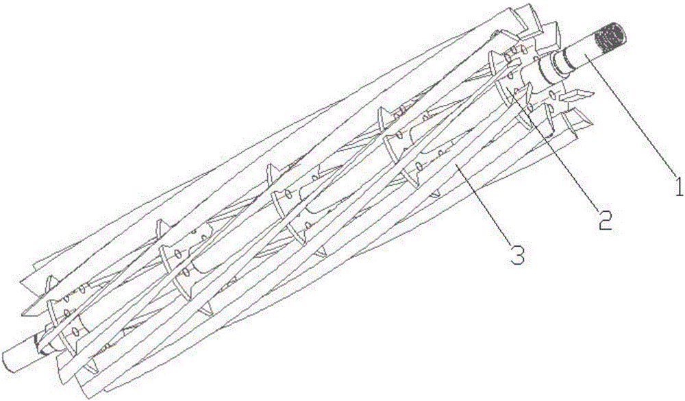
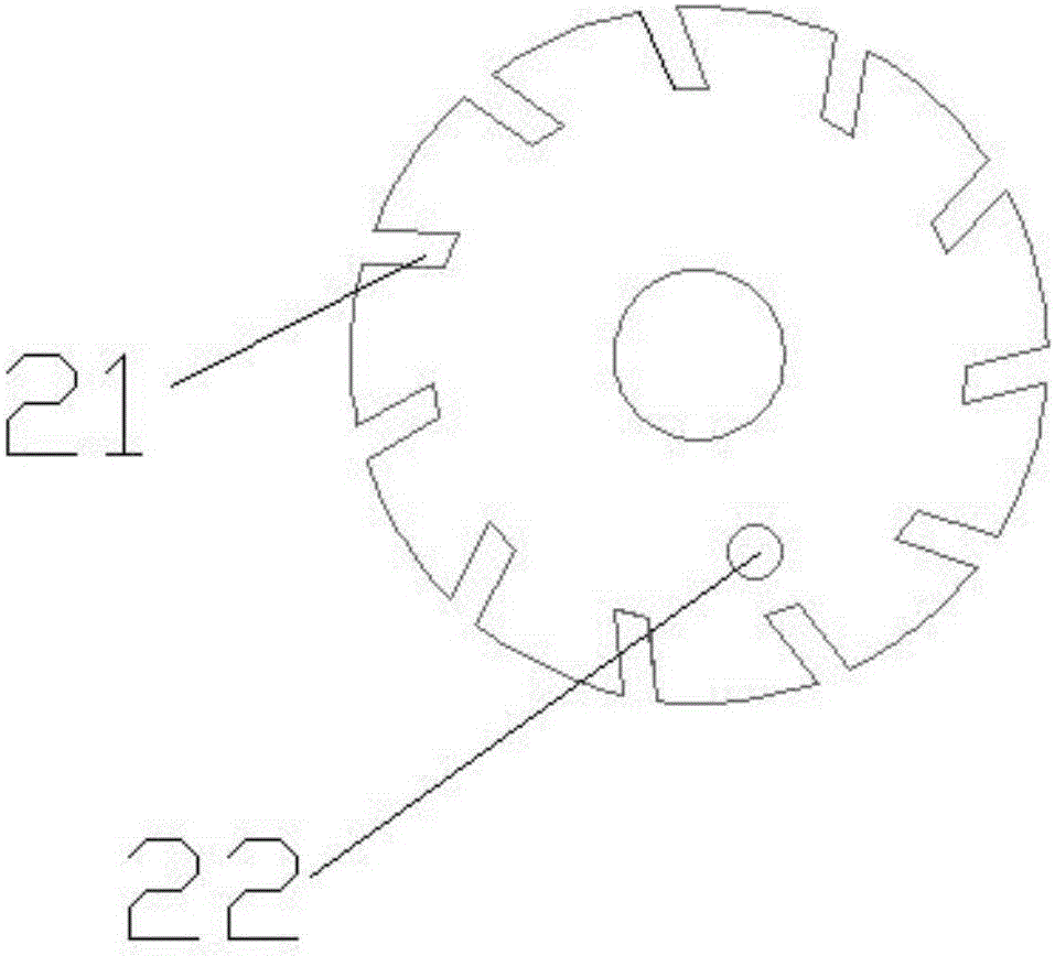
[0047] like figure 1 and figure 2Shown, a kind of mowing hob comprises main shaft 1, cutterhead 2 and blade 3, and described cutterhead 2 quantity is five, is arranged on the main shaft 1 equidistantly; Between five described cutterheads 2 The angle of rotation around the axis of the main shaft 1 differs from one end to the other by an angle of 28°; each cutter head 2 is provided with eleven slots 21, and the eleven slots 21 are formed by the cutter head 2. The center point of the surface is set on the cutter head 2 according to the 360° / 11 array of angles between items, and the number of the blades 3 is eleven; figure 1 As shown, the blade 3 is arranged on two adjacent slots on the five cutterheads whose rotation angles differ by 28°;

[0048] like figure 2 As shown, the described cutter head 2 is provided with positioning holes 22; the number of positioning holes 22 is 1 in the present embodiment, but as image 3 , ...


PUM


Abstract

The invention discloses a grass-cutting hob, a cutter welding tool of the grass-cutting hob and a manufacturing method of the grass-cutting hob, and belongs to the field of lawn machines and manufacturing processes of the lawn machines. By means of the grass-cutting hob, the cutter welding tool and the manufacturing method, the problem that existing grass-cutting hob manufacturing methods are high in cost or poor in quality is solved. The grass-cutting hob comprises cutters. Multiple insertion grooves are formed in each cutter. The corresponding insertion grooves are formed in each cutter with the circle center of the surface of the cutter as the central point according to an array with the angles between items being a. Positioning holes are formed in the cutters. The cutter welding tool of the grass-cutting hob comprises a base and multiple supporting plates perpendicularly arranged on the base at equal intervals. A cutter positioning block is arranged on one side of each supporting plate. The cutter positioning blocks correspond to the positioning holes. The manufacturing method of the grass-cutting hob mainly includes the step that the cutters are welded through the combination of the improvement mentioned above. The grass-cutting hob, the cutter welding tool and the manufacturing method mainly have the beneficial effect that on the premise of not increasing the production cost, the production efficiency and the quality of the grass-cutting hob are improved.

Description

technical field [0001] The invention belongs to the field of lawn machinery and its manufacturing technology, and in particular relates to a grass mowing hob and its cutterhead welding tooling and manufacturing method. Background technique [0002] The mowing reel is an important part of the reel mower, and is loved by users because of its light weight, small size, and flexible operation. The structure of the mowing hob is varied, for example, Chinese patent application number 201110431994.9, the patent document on June 26, 2013, discloses a hob type mowing mechanism, including: a moving knife part, two ends are set There are bearings, one end of which is provided with a force transmission nut connected with the output shaft of the power equipment for torque transmission; a static knife part, the static blade of which is installed on the bracket; the left support plate and the right support plate are respectively provided with There are fixed points for installation and con...

Claims


Application Information

Patent Timeline
Patent Type & Authority Applications(China)
IPC IPC(8): B23K37/04B23K31/02B23P15/00A01D34/52A01D101/00
CPCA01D34/52A01D2101/00B23K31/02B23K37/0443B23P15/00
Inventor 胡加兵
Owner MAANSHAN GREEN FRIEND MACHINE MFG
Why Eureka
Try Eureka