Magneto-rheological effect-based elevator braking device with automatic protection function and elevator braking method

A magnetorheological effect and elevator braking technology, applied in the direction of the hoisting device, etc., can solve the problems of unsatisfactory cooling effect, increased temperature of magnetorheological fluid, no design of coolant, etc., and achieve good control performance and stability. , short response time, simple and reliable control

Active Publication Date: 2017-02-15
FUZHOU UNIV
View PDF7 Cites 8 Cited by
  • Summary
  • Abstract
  • Description
  • Claims
  • Application Information

AI Technical Summary

Problems solved by technology

At the same time, in the original magneto-rheological brake, there is no heat dissipation channel for the cooling fluid. During the braking process of the brake, the mechanical energy is converted into heat energy, which causes the temperature of the magneto-rheological fluid to rise, so cooling and heat dissipation are necessary.
According to the Chinese patent CN203702929U, the name is "a water-cooled magneto-rheological brake". The water tanks are processed on the end covers on both sides, and the heat is dissipated through water circulation. However, due to the large distance between the coolant flow channel and the magnetorheological fluid, in During the braking process, the magnetorheological fluid is still at a relatively high temperature, and the cooling effect is not ideal. In this magnetorheological brake, an internal coolant flow channel is added to dissipate heat from the coolant, which has a better cooling and heat exchange effect

Method used


Image

  • Magneto-rheological effect-based elevator braking device with automatic protection function and elevator braking method
  • Magneto-rheological effect-based elevator braking device with automatic protection function and elevator braking method
  • Magneto-rheological effect-based elevator braking device with automatic protection function and elevator braking method

Examples


Embodiment Construction

[0028] The present invention will be further explained in conjunction with the accompanying drawings and specific embodiments.

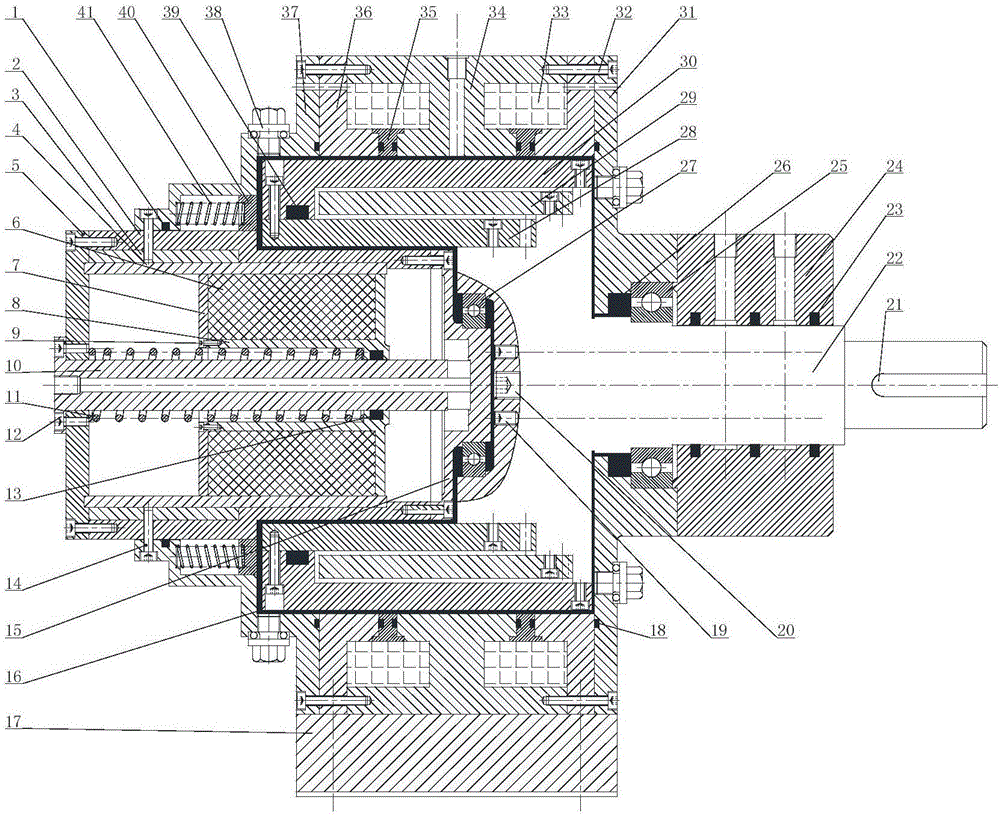
[0029] The invention provides an elevator braking device with automatic protection function based on the magneto-rheological effect, which includes a rotor assembly and a stator assembly, the rotor assembly is fixed on the stator assembly through a bearing, and the rotor assembly includes a brake Shaft and rotating sleeve; the stator assembly includes a rotating shaft end cover, an excitation structure, an outer end cover-permanent magnet, a permanent magnet structure and a base; one side of the excitation structure is fixedly connected with the outer end cover-permanent magnet, and the other side It is fixedly connected with the end cover of the rotating shaft, and forms a gap with the rotating sleeve of the rotor assembly; the permanent magnet structure is in contact with the rotor assembly through the bearing, and is fixed on the stator assembly th...


PUM


Abstract

The invention provides a magneto-rheological effect-based elevator braking device with the automatic protection function and an elevator braking method. The device adopts a structure combining a permanent magnet and common magnet exciting coils. On the normal operation condition, the braking torque of a brake is controlled by controlling currents of the magnet exciting coils, on the emergency conditions, the permanent magnet can move towards the direction of magneto-rheological fluid under the pressure of a reset spring by cutting off compressed air entering a permanent magnet-air inlet cylinder, and therefore a magnetic field of the permanent magnet can be exerted on the magneto-rheological fluid, then the braking torque can be generated and the braking effect can be realized. According to the magneto-rheological effect-based traction elevator braking device, an internal cooling liquid flow channel is used for dissipating heat, the magneto-rheological fluid can be maintained within a low temperature range, and good control performance and good stability performance can be obtained. The magneto-rheological effect replaces an original mechanical brake, and therefore control over the braking device is simple and reliable.

Description

technical field [0001] The invention relates to a traction elevator braking device and method based on magneto-rheological effects, in particular to a traction elevator braking device and method using permanent magnets and coils as excitation devices and applying them to magnetorheological fluids. Background technique [0002] An elevator is a vertical elevator powered by a motor, which can be used in multi-storey buildings to take advantage of people or carry goods. With the rapid development of high-rise buildings, the demand for elevators is increasing. High-performance elevator technology improves people's work efficiency and life experience. Elevators are special equipment, and their safety performance must be guaranteed during use. At the same time, they also need to meet the needs of comfort, energy saving, environmental protection, and low noise. However, the current electromagnetic traction elevator brakes have some shortcomings such as mechanical wear, vibration an...

Claims


Application Information

Patent Timeline
Patent Type & Authority Applications(China)
IPC IPC(8): B66D5/28
CPCB66D5/28
Inventor 陈淑梅陈凯峰蔡文杰朱佳林林宏磊
Owner FUZHOU UNIV
Why Eureka
Try Eureka