
Waste heat recovery device for ascending pipe of coke oven

A waste heat recovery device and coke oven technology, which is applied in the heating of coke ovens, coke ovens, carbonization gas discharge devices, etc., can solve problems such as large ammonia water, waste of water resources and electricity, and increase sewage discharge, so as to ensure safety Operation, avoid coking, reduce the effect of dosage

Inactive Publication Date: 2017-02-15
HUATIAN ENG & TECH CORP MCC +1
View PDF8 Cites 8 Cited by
  • Summary
  • Abstract
  • Description
  • Claims
  • Application Information

AI Technical Summary

Problems solved by technology

This process not only wastes a lot of raw gas sensible heat, but also consumes a lot of ammonia water, wastes a lot of water resources and electricity, and increases the amount of sewage discharge
[0003] The sensible heat of raw coke oven gas is huge and has not been effectively utilized

Method used


Image

  • Waste heat recovery device for ascending pipe of coke oven
  • Waste heat recovery device for ascending pipe of coke oven

Examples


Embodiment 1

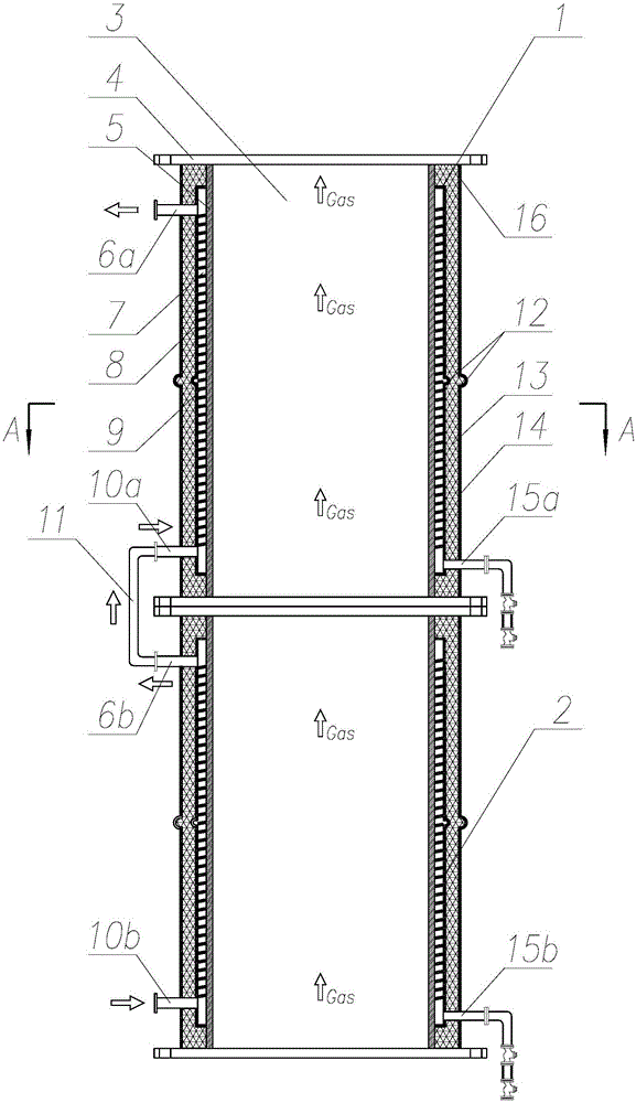
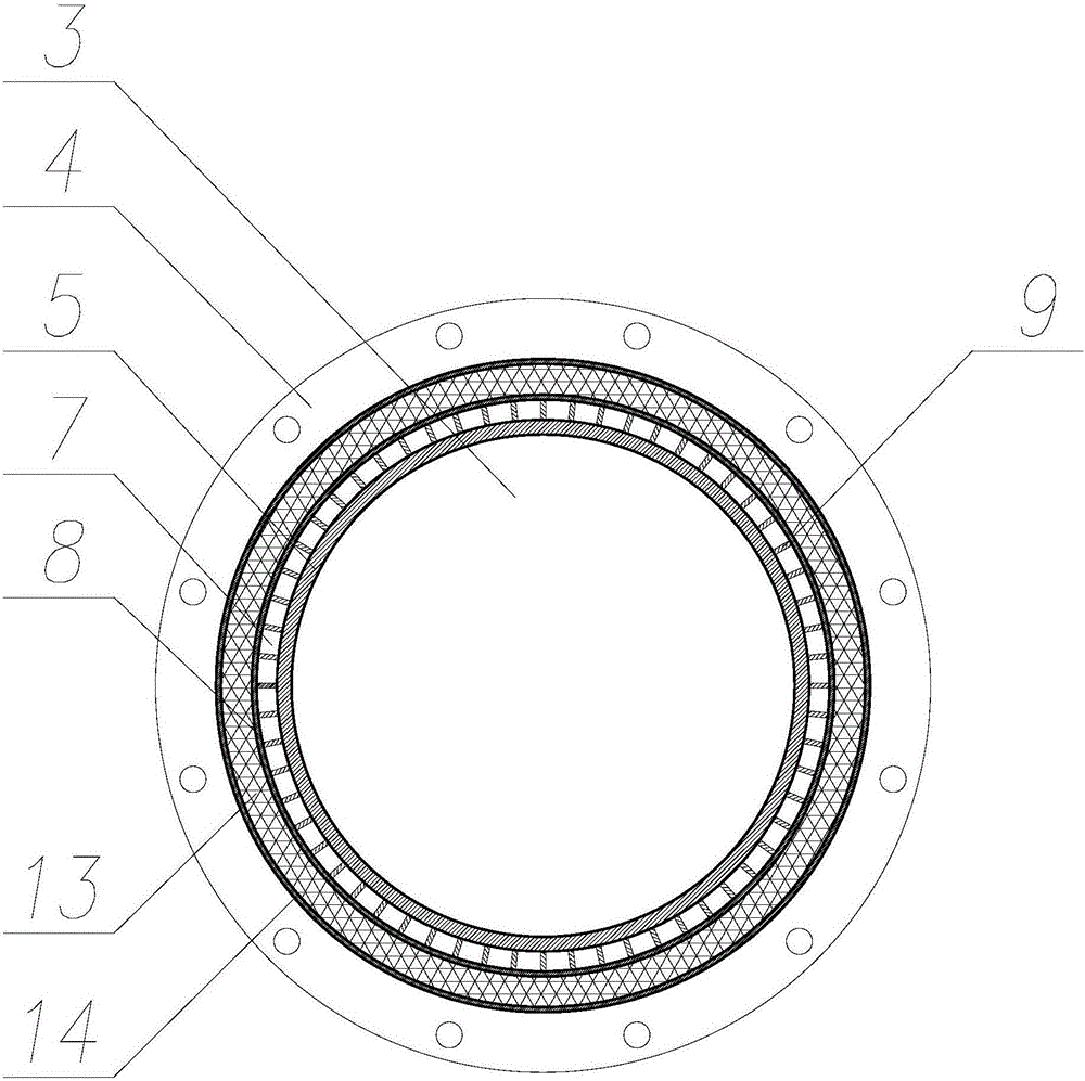
[0025] Such as Figure 1-2 As shown, the present embodiment provides a coke oven riser gas waste heat recovery device, the device includes two coke oven riser evaporators 1, 2; wherein the coke oven riser evaporator 1 adopts a jacket structure, It is composed of coke oven raw gas channel 3, inner pipe 5, steam water channel 7, inner casing 8, insulation layer 13, outer jacket 14, etc. The central tube is a cylindrical raw gas channel 3, and the inner pipe wall 5 is coated Layer to prevent coking, and at the same time as the main heating surface.

[0026] The pipe wall jacket is a steam-water channel 7, and the steam drum feedwater absorbs the heat of the rising tube evaporator in the jacket to generate a steam-water mixture; the inside of the rising tube evaporator is provided with a cooling water diversion structure 9, which can make the inside of the jacket The soda flow field is evenly distributed.

[0027] The inner tube 5 and the inner casing 8 of the riser tube evapora...

Embodiment 2

[0031] The difference between this embodiment and Embodiment 1 is that corrugated compensators 12 are provided on the outer wall 8 of the inner casing and the outer jacket 14 respectively. A balance hole 16 is provided on the upper side of the outer jacket.

[0032] Since the inner pipe 5, the inner sleeve 8, and the outer jacket 14 have different heating degrees and different materials, a corrugated compensator is provided on the inner sleeve 8 and the outer jacket 14 in this embodiment to Compensate for the deformation difference caused by the expansion and contraction ratio among the three, and avoid damage to the riser heat exchanger.

Embodiment 3

[0034] On the basis of the above-mentioned embodiments, each spoiler 9 is arranged in a spiral in the soda channel, and the spoilers 9 are arranged at intervals between two adjacent spoilers 9 , and the spoilers 9 on two adjacent spiral tracks are arranged alternately.

[0035] The setting method of the spoiler 9 in this embodiment can make the heat exchange medium spontaneously select the flow mode according to its temperature. If the temperature of the medium is high and the rising ability is strong, it will rise directly from the space between the spoiler 9. If The temperature of the medium is relatively low, and its rising ability is weak. It will flow along the spiral channel and extend the heat exchange path, so as to ensure the sufficient heat exchange of the medium.


PUM


Abstract

The invention discloses a waste heat recovery device for an ascending pipe of a coke oven. The waste heat recovery device comprises two or more ascending pipe evaporators which are communicated sequentially, wherein the ascending pipe evaporators comprise inner pipes, inner sleeves, thermal insulation layers and outer jackets which are sequentially arranged from inside to outside, crude gas channels are arranged on the inner sides of the inner pipes, the top ends of the inner sleeves are in tight connection with the top ends of the inner pipes, the bottom ends of the inner sleeves are in tight connection with the bottom ends of the inner pipes, and gas-water channels are formed between the inner pipes and the inner sleeves; gas-water outlets are formed in the tops, corresponding to the gas-water channels, of the inner sleeves and penetrate through the thermal insulation layers and the outer jackets; gas-water inlets are formed in the bottoms, corresponding to the gas-water channels, of the inner sleeves and penetrate through the thermal insulation layers and the outer jackets; and the gas-water outlet of each ascending pipe evaporator is communicated with the gas-water inlet of the upper adjacent ascending pipe evaporator. According to the waste heat recovery device, the matching between the crude gas quantity and the waste heat recovery capacity of the device is realized.

Description

technical field [0001] The invention relates to a coke oven riser waste heat recovery device. Background technique [0002] During the coking process of the coke oven, a large amount of raw gas escapes from the carbonization chamber, which is cooled and collected by the coke oven riser pipe, bridge pipe, and gas collection pipe, and then sent to the chemical production device for purification treatment; during a coking cycle, the single-hole carbonization chamber produces The output of raw gas is about 10000m3, and the temperature of raw gas is as high as 650-800°C when it passes through the coke oven riser, which contains a lot of sensible heat. In order to reduce the temperature of coke oven raw gas to facilitate the subsequent coking process, the traditional process uses spraying and circulating ammonia water to rapidly cool the high-temperature raw gas, so that the temperature of the raw gas is reduced to 80-85°C. This technological process not only wastes a large amoun...

Claims


Application Information

Patent Timeline
Patent Type & Authority Applications(China)
IPC IPC(8): C10B27/00F27D17/00
CPCC10B27/00F27D17/004Y02P10/25Y02P20/129
Inventor 王浩詹茂华余波李明夏溢
Owner HUATIAN ENG & TECH CORP MCC
Learn More