Manufacturing method of offshore wind turbine base
A technology for wind turbines and seabeds, which is applied in the directions of installing/supporting the configuration of wind turbines, wind power generation, engine components, etc., can solve the problem of high cost of base construction, and achieve convenient transportation and installation, improved alloy strength, and increased strength. Effect
- Summary
- Abstract
- Description
- Claims
- Application Information
AI Technical Summary
Problems solved by technology
Method used
Image

Examples
Embodiment 1
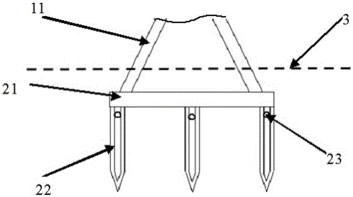
[0036] A method for preparing an offshore wind generator base, the wind generator base includes a tower lower end and a seabed foundation.
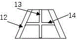
[0037] The lower end of the tower tube is hollow in the shape of a truncated cone, including a tube wall, an inner rod and a crossbeam. for connecting the barrel wall and the inner rod.
[0038] The seabed foundation includes a support part affixed to the circular platform at the lower end of the tower and a conical column embedded in the seabed. There are 8 conical columns, the upper ends of which are all affixed to the support part, and the lower end Wedge into the seabed, the tapered column is a hollow structure, the upper section is cylindrical, the lower section is conical, and filler injection ports are arranged on the top side.
[0039] The material of the tapered column is high-strength stainless steel, and the high-strength stainless steel is calculated by mass percentage: C: 0.03%, Si: 0.6~1.0%, Mn: 1.5%, Cr: 6.2%, Ni: 2.3%, N...
Embodiment 2
[0056] A method for preparing an offshore wind generator base, the wind generator base includes a tower lower end and a seabed foundation.
[0057] The lower end of the tower tube is hollow in the shape of a frustum of a cone, including a tube wall, an inner rod and a crossbeam. for connecting the barrel wall and the inner rod.
[0058] The seabed foundation includes a support part affixed to the circular platform at the lower end of the tower and a conical column embedded in the seabed. There are 10 conical columns, the upper ends of which are all affixed to the support part, and the lower end Wedge into the seabed, the tapered column is a hollow structure, the upper section is cylindrical, the lower section is conical, and filler injection ports are arranged on the top side.
[0059] The material of the tapered column is high-strength stainless steel, and the high-strength stainless steel is calculated by mass percentage: C: 0.05%, Si: 0.8%, Mn: 1.6%, Cr: 6.8%, Ni: 2.5%, N:...
Embodiment 3
[0078] A method for preparing an offshore wind generator base, the wind generator base includes a tower lower end and a seabed foundation.
[0079] The lower end of the tower tube is hollow in the shape of a frustum of a cone, including a tube wall, an inner rod and a crossbeam. for connecting the barrel wall and the inner rod.
[0080] The seabed foundation includes a support part affixed to the circular platform at the lower end of the tower and a conical column embedded in the seabed. There are 8 conical columns, the upper ends of which are all affixed to the support part, and the lower end Wedge into the seabed, the tapered column is a hollow structure, the upper section is cylindrical, the lower section is conical, and filler injection ports are arranged on the top side.
[0081] The material of the tapered column is high-strength stainless steel, and the high-strength stainless steel is calculated by mass percentage: C: 0.06%, Si: 0.9%, Mn: 1.9%, Cr: 6.9%, Ni: 2.68%, N:...
PUM
| Property | Measurement | Unit |
|---|---|---|
| thickness | aaaaa | aaaaa |
| tensile strength | aaaaa | aaaaa |
| tensile strength | aaaaa | aaaaa |
Abstract
Description
Claims
Application Information
 - R&D
- Intellectual Property
- Life Sciences
- Materials
- Tech Scout
- Unparalleled Data Quality
- Higher Quality Content
- 60% Fewer Hallucinations
Browse by: Latest US Patents, China's latest patents, Technical Efficacy Thesaurus, Application Domain, Technology Topic, Popular Technical Reports.
© 2025 PatSnap. All rights reserved.Legal|Privacy policy|Modern Slavery Act Transparency Statement|Sitemap|About US| Contact US: help@patsnap.com