Method for detecting deep ultraviolet laser radiation induction surface change of CaF2 optical substrate

A technology of laser radiation and change detection, applied in fluorescence/phosphorescence, Raman scattering, material excitation analysis, etc., can solve the degradation of microscopic imaging clarity, difficult to accurately locate damage morphology, observation and accurate judgment of surface morphology difficulties, etc.

Active Publication Date: 2017-02-15
CHANGCHUN INST OF OPTICS FINE MECHANICS & PHYSICS CHINESE ACAD OF SCI
View PDF9 Cites 7 Cited by
  • Summary
  • Abstract
  • Description
  • Claims
  • Application Information

AI Technical Summary

Problems solved by technology

In the actual test, the differential interference microscopy method has the following two shortcomings: when the radiation point damage of the sample is not obvious, its damage morphology is difficult to be accurately located in the off-line microscope; due to its relatively weak illumination intensity and the focus of the observation surface The problem is that when the magnification exceeds 100 times, the clarity of the microscopic imaging will degrade, making it difficult to observe and accurately judge the surface topography, and it is difficult to observe and judge smaller or weak damage topography
Obviously, the current international standard ISO 21254 cannot well meet the needs of this application

Method used


Image

  • Method for detecting deep ultraviolet laser radiation induction surface change of CaF2 optical substrate
  • Method for detecting deep ultraviolet laser radiation induction surface change of CaF2 optical substrate

Examples


Embodiment Construction

[0022] In order to make the object, technical solution and advantages of the present invention clearer, the present invention will be further described in detail below in conjunction with the accompanying drawings and specific embodiments. It should be understood that the specific embodiments described here are only used to explain the present invention, but not to limit the present invention.

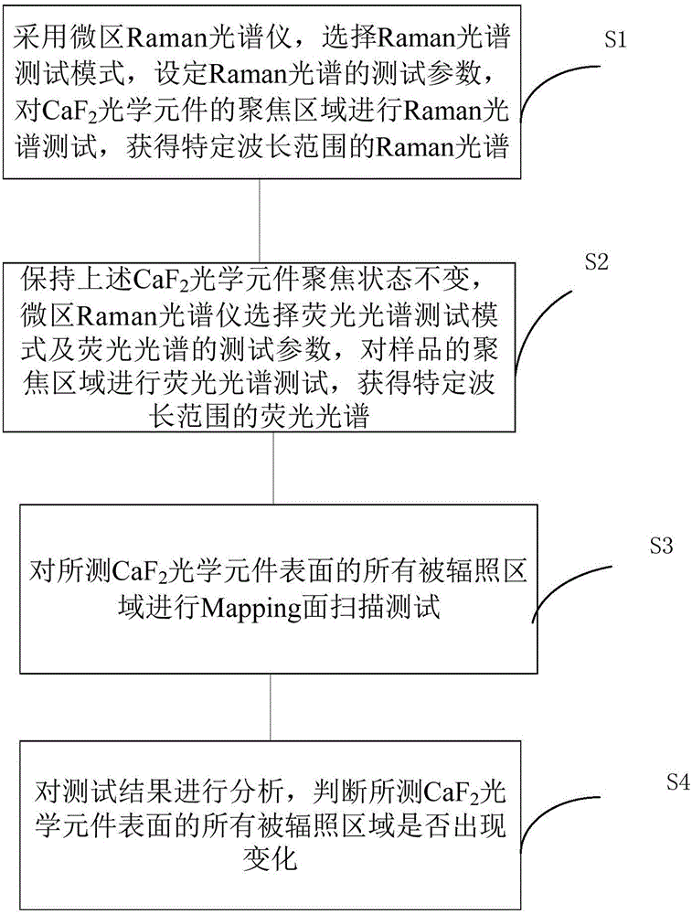
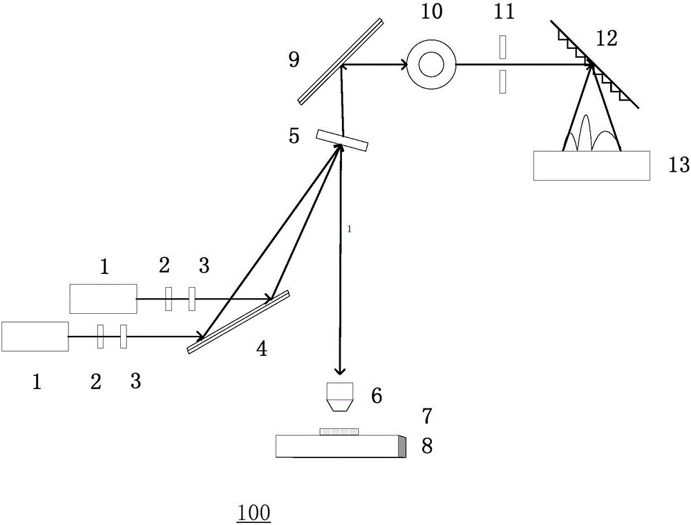
[0023] Refer below Figure 1 to Figure 2 To the CaF of the embodiment of the present invention 2 A method for detecting surface changes induced by deep ultraviolet laser radiation on optical substrates is described in detail.

[0024] Raman spectroscopy and fluorescence spectroscopy are two relatively mature techniques for the study of crystal materials and surfaces, and have been widely used in the characterization of various materials. For long-term irradiation of CaF with high repetition rate and low energy density deep ultraviolet laser 2 The irradiated surface of the optical el...


PUM

PropertyMeasurementUnit
wavelengthaaaaaaaaaa

Abstract

The invention discloses a method for detecting a deep ultraviolet laser radiation induction surface change of a CaF2 optical substrate. The method comprises the following steps: S1, carrying out a Raman spectrum test on a focus area of a CaF2 optical element by using a micro Raman spectroscopy, selecting a Raman spectrum test mode and setting a Raman spectrum test parameter; S2, selecting a fluorescence spectrum test mode and a fluorescence spectrum test parameter by the micro Raman spectroscopy, and carrying out a fluorescence spectrum test on the focus area of a sample; S3, carrying out a Mapping surface scanning test on all irradiated areas of the surface of the tested CaF2 optical element; S4, analyzing test results and judging whether all irradiated areas of the surface of the tested CaF2 optical element change. The method for detecting the deep ultraviolet laser radiation induction surface change of the CaF2 optical substrate provided by the invention can improve the detection precision and the detection accuracy.

Description

technical field [0001] The invention relates to the field of surface detection of optical components, in particular to a CaF 2 Method for detecting surface changes induced by deep ultraviolet laser radiation on optical substrates. Background technique [0002] In recent years, deep ultraviolet lasers including ArF excimer lasers have been used in industrial applications including fine microprocessing of materials, deep ultraviolet lithography, material processing, laser marking, etc., excimer laser medical treatment, and scientific research and many other fields. They have been widely used more and more, especially in the field of photolithography preparation of very large scale integrated circuits, which have very important social and economic value. It is foreseeable that with the continuous development of the economy and society, deep ultraviolet lasers including ArF excimer lasers will gain more and more in-depth applications. [0003] Since the deep ultraviolet band i...

Claims


Application Information

Patent Timeline
Patent Type & Authority Applications(China)
IPC IPC(8): G01N21/65G01N21/64
Inventor 邓文渊金春水靳京城李春
Owner CHANGCHUN INST OF OPTICS FINE MECHANICS & PHYSICS CHINESE ACAD OF SCI
Why Eureka
Try Eureka