Hybrid energy storage device
A hybrid energy storage and chip technology, applied in circuit devices, AC network circuits, electrical components, etc., can solve problems such as voltage imbalance, supercapacitor and chemical power supply mutual impact, and insufficient rapid response capability
- Summary
- Abstract
- Description
- Claims
- Application Information
AI Technical Summary
Problems solved by technology
Method used
Image
Examples
Embodiment 1
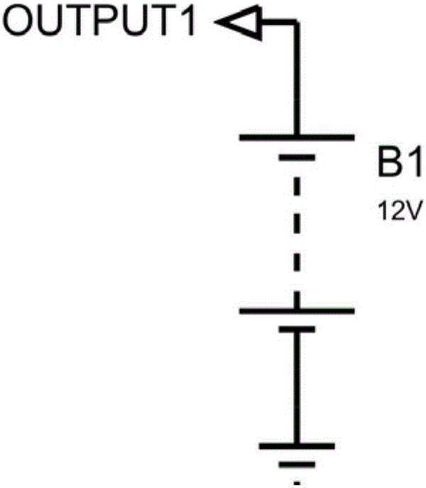
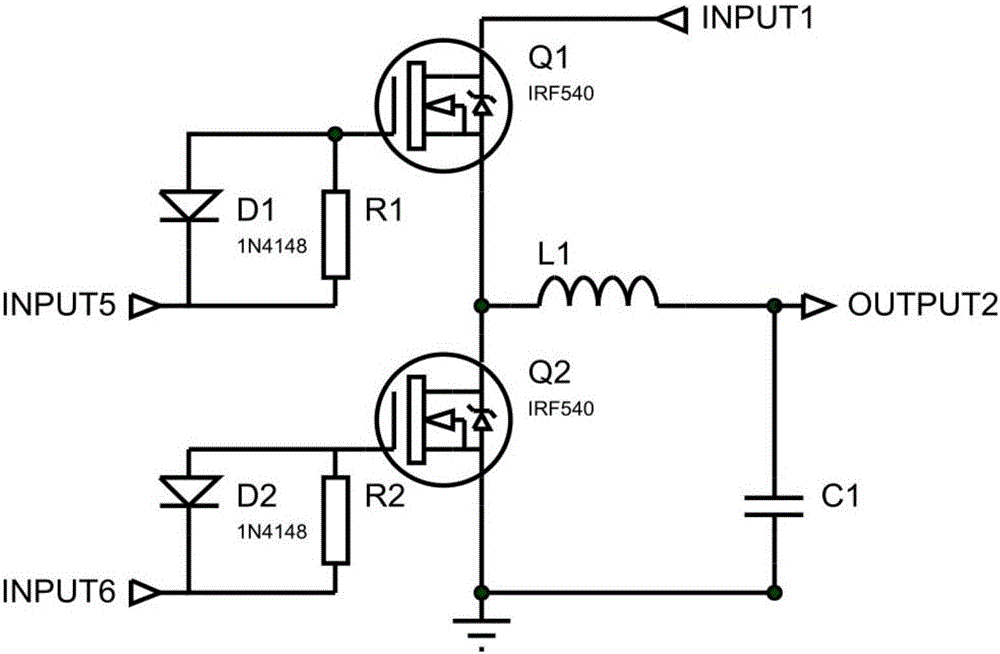
[0025] Embodiment one: if figure 1 As shown, a hybrid energy storage device includes a pulse width modulation circuit, a dead zone delay driving circuit, a power switch circuit, a sampling comparison circuit, a supercapacitor circuit and a lead-acid battery. The power switch circuit has a power supply terminal, a first input terminal , a second input terminal and an output terminal, the dead zone delay driving circuit has an input terminal, a first output terminal and a second output terminal, the positive pole of the lead-acid battery is connected to the power supply terminal of the power switch circuit, the negative pole of the lead-acid battery is grounded, The output terminal of the sampling comparison circuit is connected to the input terminal of the pulse width modulation circuit, the output terminal of the pulse width modulation circuit is connected to the input terminal of the dead zone delay driving circuit, and the first output terminal of the dead zone delay driving ...
Embodiment 2
[0026] Embodiment two: if figure 1 As shown, a hybrid energy storage device includes a pulse width modulation circuit, a dead zone delay driving circuit, a power switch circuit, a sampling comparison circuit, a supercapacitor circuit and a lead-acid battery. The power switch circuit has a power supply terminal, a first input terminal , a second input terminal and an output terminal, the dead zone delay driving circuit has an input terminal, a first output terminal and a second output terminal, the positive pole of the lead-acid battery is connected to the power supply terminal of the power switch circuit, the negative pole of the lead-acid battery is grounded, The output terminal of the sampling comparison circuit is connected to the input terminal of the pulse width modulation circuit, the output terminal of the pulse width modulation circuit is connected to the input terminal of the dead zone delay driving circuit, and the first output terminal of the dead zone delay driving ...
Embodiment 3
[0028] Embodiment three: as figure 1 As shown, a hybrid energy storage device includes a pulse width modulation circuit, a dead zone delay driving circuit, a power switch circuit, a sampling comparison circuit, a supercapacitor circuit and a lead-acid battery. The power switch circuit has a power supply terminal, a first input terminal , a second input terminal and an output terminal, the dead zone delay driving circuit has an input terminal, a first output terminal and a second output terminal, the positive pole of the lead-acid battery is connected to the power supply terminal of the power switch circuit, the negative pole of the lead-acid battery is grounded, The output terminal of the sampling comparison circuit is connected to the input terminal of the pulse width modulation circuit, the output terminal of the pulse width modulation circuit is connected to the input terminal of the dead zone delay driving circuit, and the first output terminal of the dead zone delay drivin...
PUM
 Abstract
Description
Claims
Application Information
 - R&D
- Intellectual Property
- Life Sciences
- Materials
- Tech Scout
- Unparalleled Data Quality
- Higher Quality Content
- 60% Fewer Hallucinations
Browse by: Latest US Patents, China's latest patents, Technical Efficacy Thesaurus, Application Domain, Technology Topic, Popular Technical Reports.
© 2025 PatSnap. All rights reserved.Legal|Privacy policy|Modern Slavery Act Transparency Statement|Sitemap|About US| Contact US: help@patsnap.com


