Ultrasonic coding and decoding system based on jitter sound wave signals

A sound wave signal and ultrasonic technology, applied in the field of ultrasonic coding and decoding systems, can solve problems such as low efficiency of audio signal coding operations, adjustment of audio model conversion forms, and audio quality degradation, so as to improve work efficiency and quality, improve efficiency, The effect of improving work efficiency and accuracy

Active Publication Date: 2017-02-15
新胜科技(上海)有限公司
View PDF5 Cites 2 Cited by
  • Summary
  • Abstract
  • Description
  • Claims
  • Application Information

AI Technical Summary

Problems solved by technology

[0002] At present, with the wide application of automation technology and intelligent technology in daily life, industrial production and other fields, using voice to directly control equipment has gradually become one of the important operation methods of intelligent control systems. In order to meet the long-distance audio signal To meet the needs of transmission operations, it is often necessary to encode and compile the audio into data files that can be recognized by the communication network system before transmission. In response to this need, the current compiling method is often to compress the content of the audio file, and then compress the content of the audio file. The compressed file is directly compiled into a data signal recognizable by the communication network system for transmission. Although it can meet the needs of audio model transmission, on the one hand, the work efficiency of the audio signal encoding operation is relatively low. On the other hand, the audio signal is encoded and converted. It often leads to the decline of audio quality, and even distortion in severe cases. At the same time, when restoring audio signals, the conversion form of audio models cannot be flexibly adjusted according to the needs of use. Therefore, the currently commonly used audio coding methods cannot effectively satisfy In view of the current situation, it is urgent to develop a new audio coding system to meet the needs of actual use.

Method used


Image

  • Ultrasonic coding and decoding system based on jitter sound wave signals

Examples


Embodiment Construction

[0011] In order to make the technical means, creative features, goals and effects achieved by the present invention easy to understand, the present invention will be further described below in conjunction with specific embodiments.

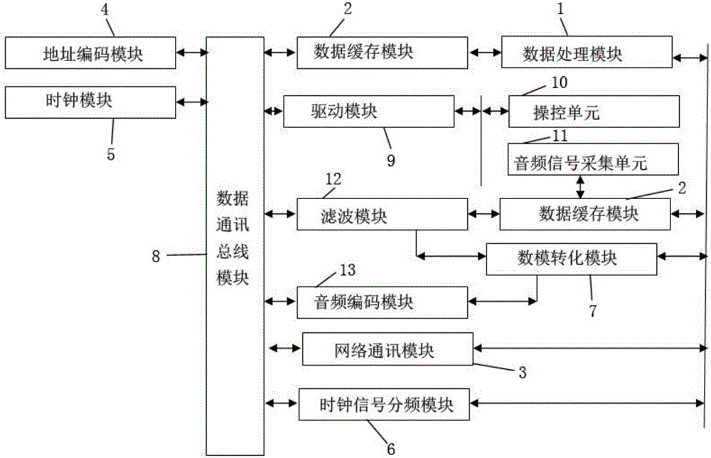
[0012] like figure 1 The described ultrasonic codec system based on trembling sound wave signals comprises a data processing module 1, a data buffer module 2, a network communication module 3, an address encoding module 4, a clock module 5, a clock signal frequency division module 6, a digital-analog Conversion module 7, data communication bus module 8, drive module 9, control unit 10, audio signal acquisition unit 11, filtering module 12 and audio encoding module 13, data communication bus module 8 is connected with data cache module 2, network communication module 3, The address coding module 4, the clock module 5, the clock signal frequency division module 6, the drive module 9, the filtering module 12 and the audio coding module 13 are electri...


PUM


Abstract

The invention relates to an ultrasonic coding and decoding system based on jitter sound wave signals. The system comprises a data processing module, a data buffer module, a network communication module, an address coding module, a clock module, a clock signal frequency division module, a digital-to-analogue conversion module, a data communication bus module, a drive module, a control unit, an audio frequency signal collection unit, a filter module and an audio frequency coding module. The data communication bus module is electrically connected with the data buffer module, the network communication module, the address coding module, the clock module, the clock signal frequency division module, the drive module, the filter module and the audio frequency coding module. The data buffer module is electrically connected with the data processing module and the audio frequency coding module. The drive module is electrically connected with the control unit and the audio frequency signal collection unit. According to the invention, the work efficiency and the accuracy of audio frequency signal coding can be effectively improved, and the efficiency of audio frequency decoding and the accuracy of audio restoration can be effectively improved.

Description

technical field [0001] The invention relates to a sound wave encoding system, specifically an ultrasonic encoding and decoding system based on vibrating sound wave signals. Background technique [0002] At present, with the wide application of automation technology and intelligent technology in daily life, industrial production and other fields, using voice to directly control equipment has gradually become one of the important operation methods of intelligent control systems. In order to meet the long-distance audio signal To meet the needs of transmission operations, it is often necessary to encode and compile the audio into data files that can be recognized by the communication network system before transmission. In response to this need, the current compiling method is often to compress the content of the audio file, and then compress the content of the audio file. The compressed file is directly compiled into a data signal recognizable by the communication network syste...

Claims


Application Information

Patent Timeline
Patent Type & Authority Applications(China)
IPC IPC(8): H04B11/00
CPCH04B11/00
Inventor 孙刚
Owner 新胜科技(上海)有限公司
Why Eureka
Try Eureka