
Acrylic fiber treatment agent and use thereof

A technology of acrylic fiber and treatment agent, applied in the direction of fiber treatment, fiber type, fiber chemical characteristics, etc., can solve the problems of broken wire operability, sintering furnace damage, narrowing of fiber bundle interval, etc., to prevent stable operability , The effect of preventing melt adhesion

Active Publication Date: 2017-02-15
MATSUMOTO YUSHI SEIYAKU
View PDF10 Cites 1 Cited by
  • Summary
  • Abstract
  • Description
  • Claims
  • Application Information

AI Technical Summary

Problems solved by technology

[0005] However, on the other hand, the silicone-based treatment agent that has undergone the adhesion treatment will fall off from the fiber and become a sticky substance, which accumulates on the drying roll or guide member in the precursor manufacturing process, which may cause the fiber to be entangled or Problems such as wire breakage that cause a decrease in operability
In addition, in the oxidizing atmosphere of the refractorization process, silicon oxide is partially formed, and when nitrogen gas is used as the inert gas in the inert atmosphere of the carbonization process, silicon nitride is formed, and these scales are deposited. , there may be a problem that the operability or runnability may be reduced, or the firing furnace may be damaged.
[0006] In addition, the silicone-based treatment agent has excellent detachability based on fiber-to-fiber smoothness, which is effective in preventing fusion between single fibers, but on the other hand, when a large number of fiber bundles run in parallel In the sintering process, the width of each fiber bundle becomes wider due to the smoothness of the silicone-based treatment agent, and the distance between adjacent fiber bundles becomes narrower, and fluff may be generated due to interference in some cases.

Method used


Image

  • Acrylic fiber treatment agent and use thereof
  • Acrylic fiber treatment agent and use thereof
  • Acrylic fiber treatment agent and use thereof

Examples


Embodiment 1~28、 comparative example 1~13

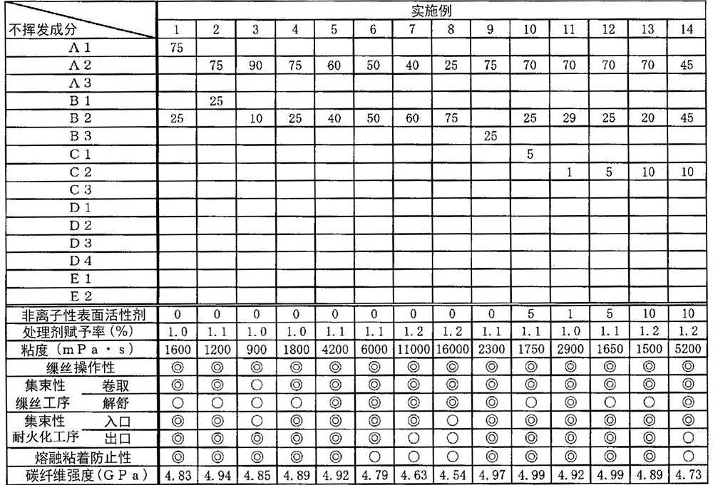
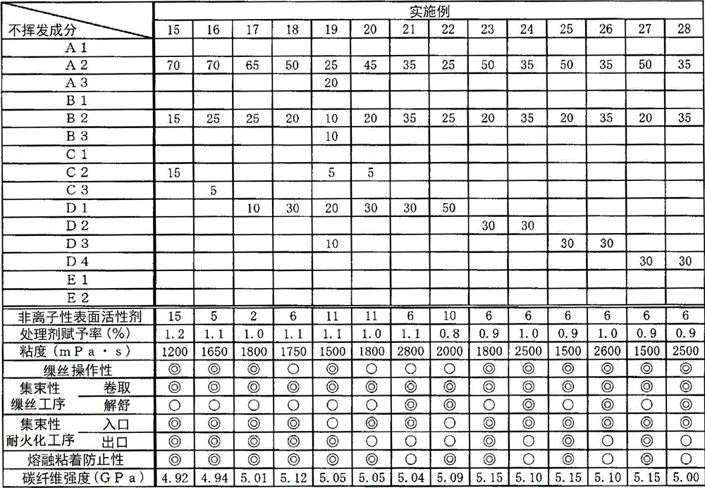
[0147] Water-based emulsification using the following compounds A1-A3, polyether compounds B1-B3, nonionic surfactants C1-C3, modified silicone D1-D4 prepared above, and ester-based compounds E1-E2 and water were mixed and stirred according to the non-volatile components shown in Tables 1 to 3 to prepare acrylic fiber treatment agents whose non-volatile components accounted for 20% by weight in the treatment agent. In addition, the numerical value in a table shows the weight ratio of each component in the non-volatile content of a processing agent. For example, the numerical values ​​of the compounds A1 to A3 in the table represent the weight ratios of the compounds A1 to A3 in the non-volatile components of the treatment agent. In addition, the numerical value of the "nonionic surfactant" of Tables 1-3 shows the weight ratio (weight%) which a nonionic surfactant (total amount) occupies in a nonvolatile component.

[0148] Next, the prepared treatment agents were further dilu...


PUM


Abstract

The purpose of the present invention is to provide an acrylic fiber treatment agent which, in the production of carbon fibers, makes it possible to achieve bundling properties of fiber bundles, to prevent fusion between the fibers and to provide stable workability. This acrylic fiber treatment agent contains a compound (A) represented by general formula (1), and a polyether compound (B) having a weight average molecular weight of 8000-25000, wherein the total weight ratio of the compound (A) and the polyether compound (B) is 50-99 wt%. In expression (1), R1 and R2 are independently a hydrogen atom or an alkyl group. AO is an oxyalkylene group of 2-4 carbon atoms. m and n are each independently a number greater than or equal to 1.

Description

technical field [0001] The invention relates to an acrylic fiber treatment agent and its application. More specifically, it relates to a treatment agent used for producing acrylic fibers, an acrylic fiber for carbon fiber production using the treatment agent (hereinafter sometimes referred to as a precursor), and a method for producing carbon fibers using the treatment agent. Background technique [0002] Carbon fibers are widely used in aerospace applications, sports applications, general industrial applications, and the like as reinforcing fibers for composite materials with plastics called matrix resins, taking advantage of their excellent mechanical properties. [0003] As a method for producing carbon fibers, the general method is to convert the precursor into refractory fibers in an oxidizing atmosphere at 200-300°C, and then perform carbonization in an inert atmosphere at 300-2000°C. During firing at these high temperatures, fusion of monofilaments occurs, resulting ...

Claims


Application Information

Patent Timeline
IPC IPC(8): D06M15/53C10M105/18C10M107/34C10M129/16C10M129/70C10M133/16C10M155/02D01F6/18D01F9/22D06M13/17D06M15/643C10N30/00C10N40/00D06M101/28
CPCC10M155/02C10M105/18C10M107/34C10M129/16C10M129/70C10M133/16D06M13/17D06M15/53D06M15/643D01F6/18D01F9/22
Inventor 菊田俊彦吉田昌彦中山武圭
Owner MATSUMOTO YUSHI SEIYAKU
Learn More