
Electron oscillation siphon type automatic spraying system

A spray system and siphon technology, applied in the direction of injection device, liquid injection device, etc., can solve the problems of high maintenance cost, high construction cost, mist loss, etc., and achieve the effect of avoiding low efficiency, small coverage area and low production cost

Inactive Publication Date: 2017-02-22
秦皇岛众鹏科技有限公司
View PDF6 Cites 1 Cited by
  • Summary
  • Abstract
  • Description
  • Claims
  • Application Information

AI Technical Summary

Problems solved by technology

There are relatively large technical defects in the existing equipment, which are mainly reflected in: The mist is transported through long-distance pipelines, and part of the mist is condensed into water, resulting in a large amount of mist loss; In long-distance pipeline transportation, a large amount of fog needs to be occupied in the pipeline, resulting in waste; Existing industrial and agricultural special humidifiers generate a large amount of mist instantaneously according to demand, which makes the structure of industrial and agricultural special humidifiers complicated and bulky, requiring special equipment to be placed on the site. At the same time, because industrial and agricultural fog is multi-point Simultaneous supply requires a large amount of pipeline construction, which is difficult and costly; Due to the complex structure and large size of the existing industrial and agricultural special humidification devices, the maintenance cost is relatively high; The purchase cost of existing industrial and agricultural special humidification devices is high
[0004] Generally speaking, the existing industrial and agricultural special humidification devices have technical defects such as high cost, difficult construction, low efficiency of mist use, and high maintenance cost.

Method used


Image

  • Electron oscillation siphon type automatic spraying system
  • Electron oscillation siphon type automatic spraying system

Examples


Embodiment Construction

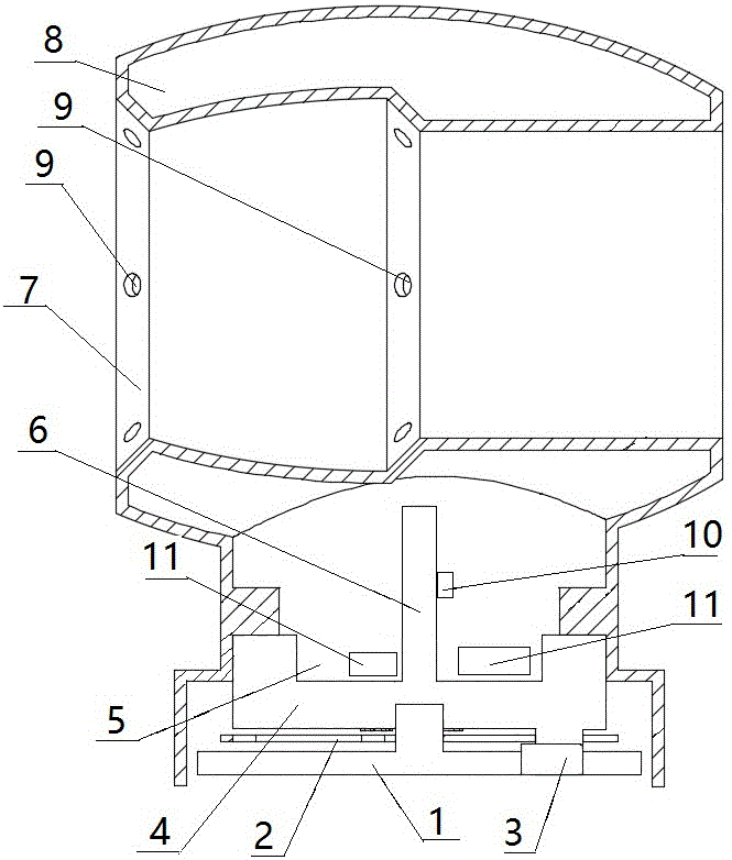
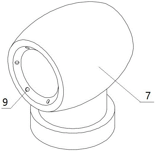
[0033] In order to describe the technical solution of the present invention in more detail, the technical solution of the present invention will be described in detail below in conjunction with the accompanying drawings.

[0034] Such as figure 1 and figure 2 As shown, an electronic oscillating siphon automatic spray system according to the present invention includes a background control system, an environmental information acquisition unit group and an electronic oscillating siphon sprayer group; each electronic oscillating siphon sprayer corresponds to an environmental information acquisition unit ;

[0035] The electronic oscillating siphon spray and the environmental sensor group are electrically connected to the background control system;

[0036] The background control system stores the number of each electronic oscillating siphon sprayer, and the background control system presets and stores the environmental information threshold value around each electronic oscillat...


PUM


Abstract

An electron oscillation siphon type automatic spraying system comprises a background control system, an environment information acquisition unit group and an electron oscillation siphon type sprayer group. The electron oscillation siphon type sprayer group and an environment sensor group are electrically connected to the background control system. Different point position environment information threshold values are preset in the background control system. Environment information acquisition units acquire environment information in real time. The background control system receives the information, and electron oscillation siphon type sprayers execute corresponding operations according to instruction of the background control system. The electron oscillation siphon type automatic spraying system has the beneficial effects that spraying to different points can be independently controlled in real time according to environment requirements, and systematic automatic spraying management is achieved. The spraying system is simple in structure, easy to manufacture, and low in production cost; the minitype spraying system is adopted, so that spraying to the different points can be handled independently; and the spraying system has the characteristics of being easy to construct, low in construction cost and convenient to maintain.

Description

technical field [0001] The invention belongs to the field of environmental protection and the technical field of pollution control equipment, in particular to an electronic oscillating siphon type automatic spraying system. Background technique [0002] Many industries (such as pharmaceuticals, textiles, electronics, electric power, etc.), agriculture (such as cultivation bases, breeding, greenhouse planting, etc.) need to use humidifiers for environmental protection (dust suppression, urban dust suppression, etc.), the production scale is large, dedicated humidification There is a lack of professional manufacturers in the manufacture of humidifiers, and the expensive price of imported humidifiers and high maintenance costs make it unaffordable for most small businesses. [0003] In addition, the existing industrial and agricultural special humidification devices all generate mist by special large-scale equipment, and then pipe it to the place where it is needed. There are ...

Claims


Application Information

Patent Timeline
Patent Type & Authority Applications(China)
IPC IPC(8): B05B17/06B05B12/08B05B12/12B05B15/04
CPCB05B12/081B05B12/12B05B17/0607B05B17/0676B05B12/18
Inventor 毛邦树
Owner 秦皇岛众鹏科技有限公司
Learn More