Semi-automatic vibrating table

A semi-automatic, vibrating table technology, applied in the direction of fluid using vibration, cleaning method using gas flow, cleaning method and utensils, etc., can solve the problems of uncontrollable vibration time, single cleaning of impurities, and high cost

Active Publication Date: 2017-02-22
SHENZHEN WAVE TELECOMM TECH CO LTD
View PDF5 Cites 4 Cited by
  • Summary
  • Abstract
  • Description
  • Claims
  • Application Information

AI Technical Summary

Problems solved by technology

The mechanical vibrating table can realize low-frequency and high-amplitude motion, the electric vibrating table can realize high-frequency and low-amplitude motion, and the electro-hydraulic vibrating table can realize high-frequency and high-amplitude motion, but the cos...

Method used


Image

  • Semi-automatic vibrating table
  • Semi-automatic vibrating table
  • Semi-automatic vibrating table

Examples


Embodiment Construction

[0034] The technical solutions of the present invention will be clearly and completely described below in conjunction with the accompanying drawings. Apparently, the described embodiments are some of the embodiments of the present invention, but not all of them. Based on the embodiments of the present invention, all other embodiments obtained by persons of ordinary skill in the art without making creative efforts belong to the protection scope of the present invention.

[0035] In the description of the present invention, it should be noted that the terms "center", "upper", "lower", "left", "right", "vertical", "horizontal", "inner", "outer" etc. The indicated orientation or positional relationship is based on the orientation or positional relationship shown in the drawings, and is only for the convenience of describing the present invention and simplifying the description, rather than indicating or implying that the referred device or element must have a specific orientation, ...


PUM


Abstract

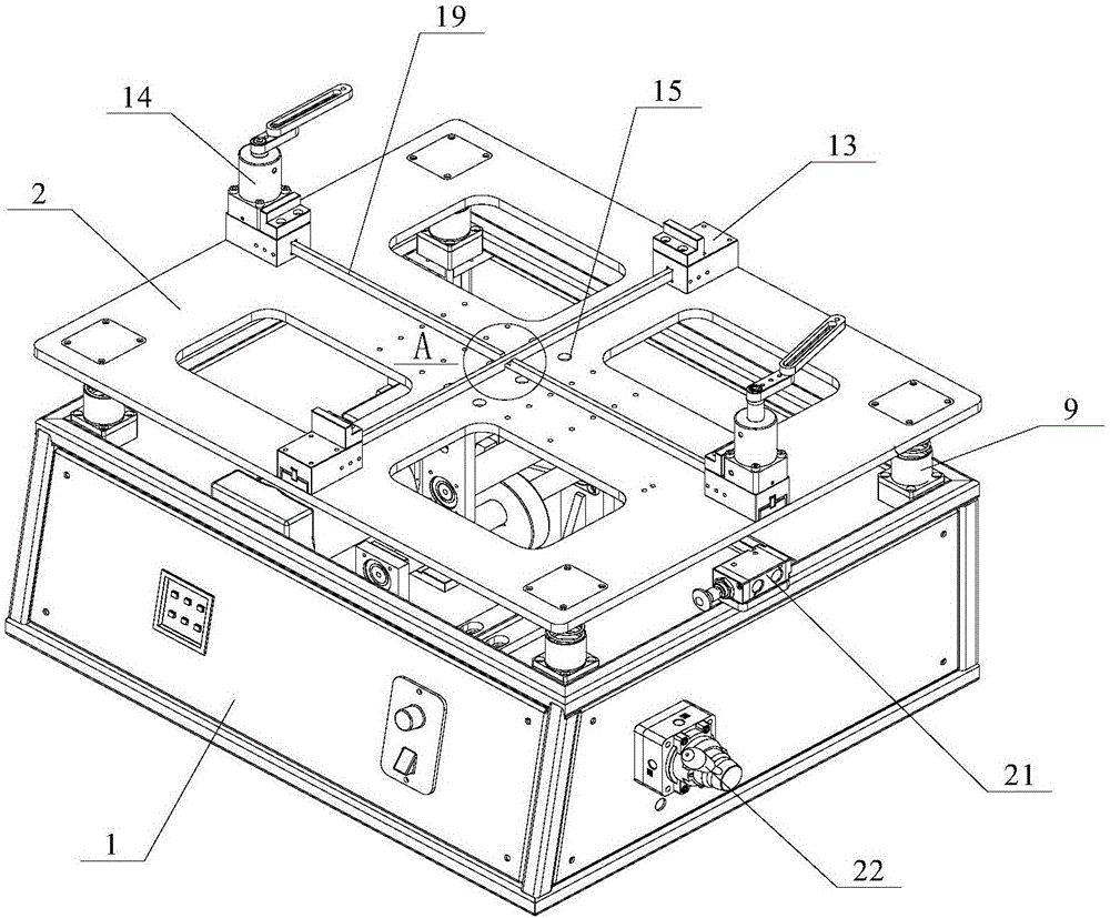
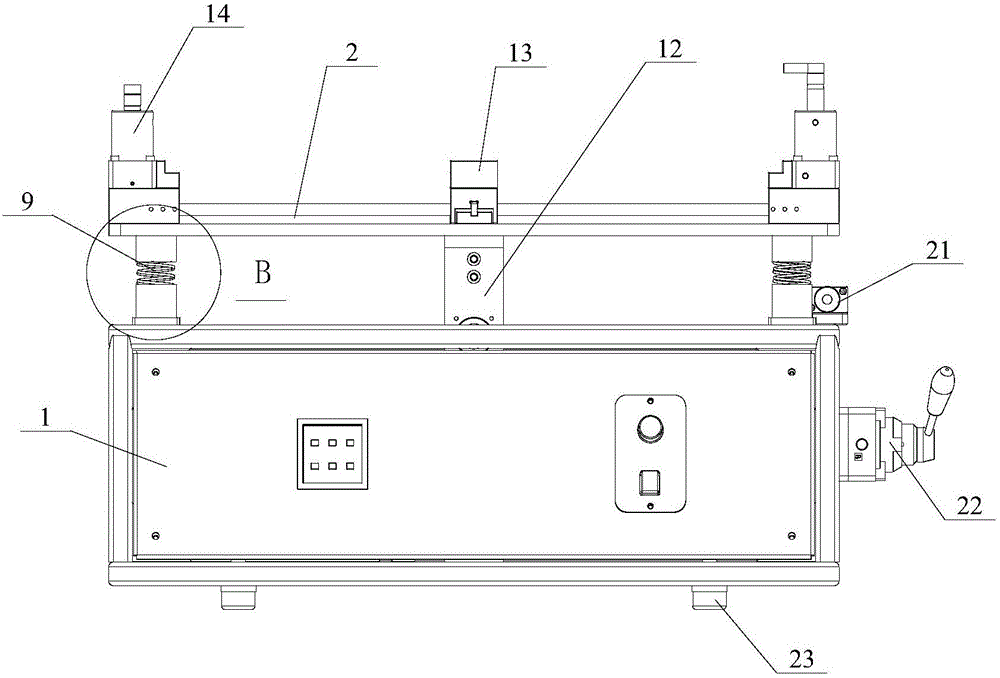
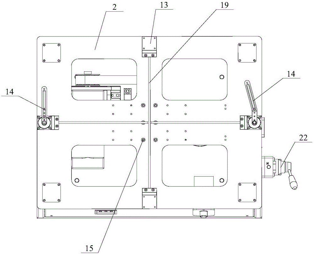
The invention provides a semi-automatic vibrating table, which relates to the technical field of vibrating device. The transmission device of the semi-automatic vibrating table includes an electrical machine arranged in the box; the output end of the electric machine connects with eccentric wheels through components of belt pulley; the vibrating device includes some groups of elastic components uniformly arranged between the workbench and the top surface of the box, and the workbench is provided with lifting components vibrating in concert with eccentric wheels; the holding device includes two groups of workbench bases arranged on the workbench, and one group of the workbench bases provided with an angular cylinder; the air-blowing device includes some air holes arranged on the workbench and an air pump using to convey gas to air holes; the controlling device includes an electric control system playing a role in controlling and a hand valve using to open and close the electric control system. The semi-automatic vibrating table realizes semi-automatic controlling through a compounding practice between the hand valve and the electric control system, in order to adjust vibrating frequency, amplitude and vibration time, and to realize final cleaning through removing dust by the air-blowing device.

Description

technical field [0001] The invention relates to the technical field of vibrating devices, in particular to a semi-automatic vibrating table. Background technique [0002] The dielectric filter is designed and manufactured by utilizing the characteristics of low loss, high dielectric constant, frequency temperature coefficient and thermal expansion coefficient of dielectric ceramic materials, and can withstand high power. line composition. The surface of the dielectric filter is covered with a metal layer with zero tangential electric field, and the electromagnetic wave is confined in the medium to form a standing wave oscillation, and its geometric size is about half of the waveguide wavelength. The material generally uses ceramics with a relative permittivity between 60 and 80, and the size of the dielectric ceramic filter actually used in wireless communication is at the centimeter level. [0003] During the production process of the dielectric filter, due to the working...

Claims


Application Information

Patent Timeline
IPC IPC(8): B08B7/02B08B5/02B08B13/00B06B1/16
CPCB06B1/162B08B5/02B08B7/02B08B13/00
Inventor 张少林吴镇生
Owner SHENZHEN WAVE TELECOMM TECH CO LTD
Why Eureka
Try Eureka