
A square hole drilling rig

A square hole drilling rig, square hole technology, applied in boring/drilling, portable drilling rig, drilling/drilling equipment, etc. Can not effectively drill square holes and other problems, to achieve the effect of sufficient positioning rigidity, small error and simple structure

Active Publication Date: 2018-09-11
马文强
View PDF9 Cites 0 Cited by
  • Summary
  • Abstract
  • Description
  • Claims
  • Application Information

AI Technical Summary

Problems solved by technology

[0003] Its shortcomings are: first, if the radius of the inferior arc bow is not the side length of the triangular plate, it is difficult to form a Leroux triangle, which will cause transmission interference or make it difficult to drill a square hole; second, the driving device passes through the variable pitch universal joint Connect the connecting shaft and the cutter head. Because the center of the cutter head is deflecting and jumping in the lateral direction during cutting, the universal joint will also follow the deflection. Yes, it violates the common sense that universal joints are suitable for transmitting torque and not for axial force transmission; third, using guide rods and suction cups for guiding and positioning will obviously not be rigid enough, because the surface of the desired drilling object is rough and uneven. The suction force is small, which is not enough to overcome the lateral deflection force generated when the cutter head is cutting, and the suction cup is easy to translate, resulting in inaccurate positioning and actually cannot effectively drill the square hole; therefore, the transmission structure of this scheme is unreasonable, and the operability is poor. Insufficient positioning rigidity, not high practicality, cannot produce positive effects

Method used


Image

  • A square hole drilling rig
  • A square hole drilling rig
  • A square hole drilling rig

Examples


Embodiment Construction

[0031] Below in conjunction with accompanying drawing, the present invention will be further described with specific embodiment, see figure 1 — Figure 9 :

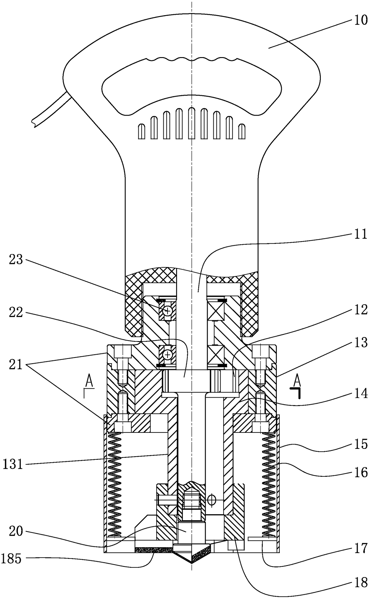
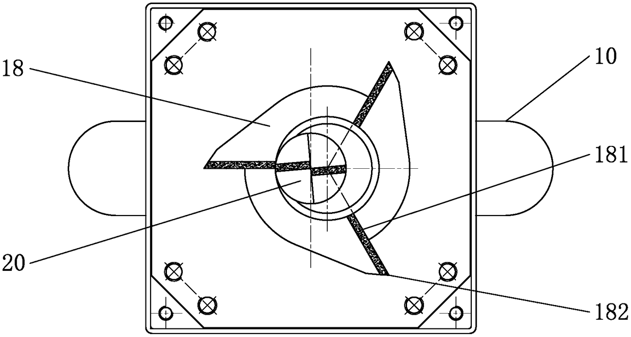
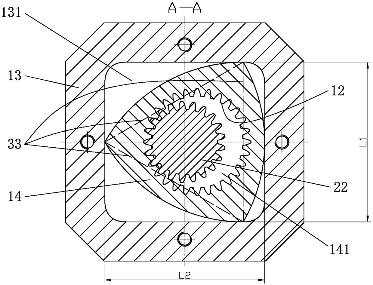
[0032] A square hole drilling machine, comprising a housing 21 and a drill bit, the drill bit is a pointed centering drill bit 20, the driving rod 11 installed in the middle of the housing 21 is supported on the housing 21 through a bearing 23, the lower end of the driving rod 11 The centering drill bit 20 is fixed coaxially, and the middle part of the driving rod 11 is provided with a pinion 22 with external teeth, and the outside of the pinion 22 is sleeved with a Relo triangular block 14 with an internal gear 12 (the described The outer contour of the Lelo triangle block 14 is a Lelo triangle, so claim the Lelo triangle block 14). The frame 13 is fixed on the housing 21, the axis center of the pinion 22 coincides with the center of the guiding frame 13, the pitch circle diameter of the internal gear 12 is larger than...


PUM


Abstract

The invention belongs to the technical field of hole opening equipment and relates to a square hole drilling machine. The machine comprises a casing and a bit; a driving rod mounted in the middle of the casing is connected; a centering bit is fixed at the lower end of the driving rod; a pinion is arranged in the middle of the driving rod; the outer side of the pinion is sleeved with a Reuleaux triangle block; the Reuleaux triangle block is placed in a central square hole of a square guiding frame; the square guiding frame is fixed on the casing; the pinion is in meshed transmission with an inner gear; a hollow square hole milling cutter is arranged at the lower end of the Reuleaux triangle block; and the lower end of the centering bit is located below the lower end surface of the square hole milling cutter. The machine has the advantages as follows: the centering bit is adopted for direct hole drilling centering, labor-saving operation is realized, the centering accuracy is high, the rejection rate is low, by the aid of the guiding structure of the Reuleaux triangle and the square hole milling cutter, drilled square holes have the small error and the high quality and is standard, noise is low, and the machine is applicable to drilling of the square holes.

Description

technical field [0001] The invention belongs to the technical field of drilling equipment, in particular to a square hole drilling machine. Background technique [0002] Chinese patent CN 105598502 A discloses "A Device for Opening Square Holes", which includes a fixed frame, which is a square hole, and the four corners of the hole are rounded transitions, and a guide seat is provided in the fixed frame, and the guide seat is formed by a square hole. Composed of a triangular plate and three bow-shaped plates, the bow-shaped plate is an inferior arc bow, the chord of each bow-shaped plate matches the side of the regular triangular plate, the triangular plate and the bow-shaped plate are integrated structure; one side of the fixed frame is installed with a support frame, and the support frame Install the rotary drive device, the output shaft of the rotary drive device is connected to one end of the variable pitch universal joint, the other end of the variable pitch universal j...

Claims


Application Information

Patent Timeline
Patent Type & Authority Patents(China)
IPC IPC(8): B23B41/04B23B45/02B23B45/04B23B51/08
CPCB23B41/04B23B45/02B23B45/04B23B51/08
Inventor 马文强
Owner 马文强
Learn More