Bionic robotic fish

A technology of robotic fish and fish fins, applied in the field of bionic robotic fish, can solve problems such as complex dynamic sealing structure, damaged engine, high manufacturing cost, etc., and achieve the effects of reducing leakage risk, minimum effort, and low cost

Inactive Publication Date: 2017-02-22
NORTHWEST UNIV
View PDF9 Cites 1 Cited by
  • Summary
  • Abstract
  • Description
  • Claims
  • Application Information

AI Technical Summary

Problems solved by technology

Due to the pressure and fluidity of water, this kind of energy supply system is faced with the risk of seal failure caused by friction between the propeller, gear or other rotating parts and the motor structure, resulting in water ingress, electric leakage, engine damage, etc. In order to avoid such Risk, the current underwater machines all use mechanical dynamic seals, but dynamic seals have disadvantages such as complex structure, high manufacturing cost, and difficult processing, so it is difficult to popularize the technology to the field of ordinary underwater toys

Method used


Image

  • Bionic robotic fish
  • Bionic robotic fish
  • Bionic robotic fish

Examples


Embodiment Construction

[0049] Specific embodiments of the present invention will be described in detail below.

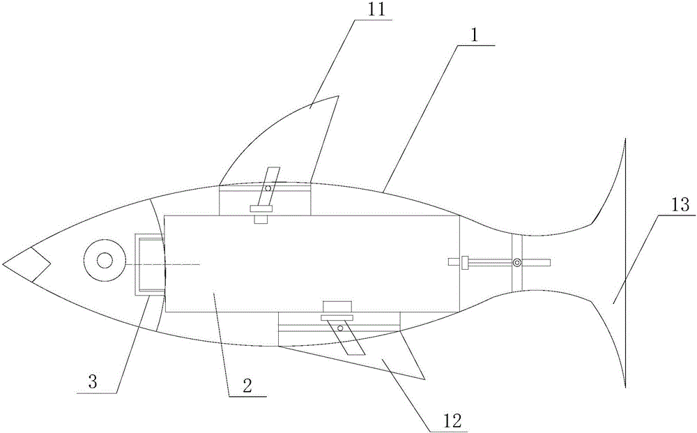
[0050] Such as Figure 1~5 Shown, a kind of bionic robot fish comprises:

[0051] Shell 1,

[0052] The upper fin 11 is fixed on the top of the shell 1,

[0053] The lower fin 12 is fixed on the bottom of the shell 1,

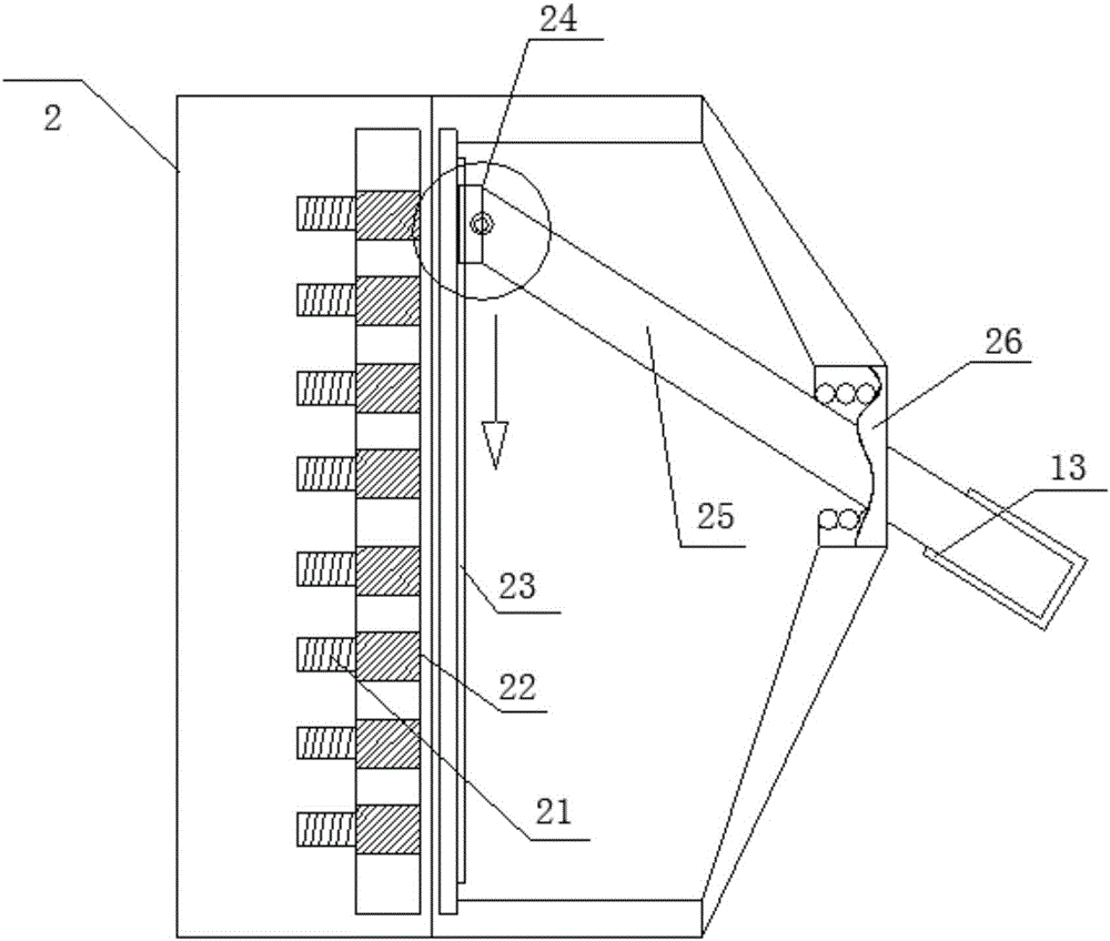
[0054] The fish tail 13 is fixed on the tail of the shell 1,

[0055] The copper shell 2 is located inside the shell 1, and the side wall at one end of the copper shell 2 is provided with external threads,

[0056] Sealing cover 3, its inner side is provided with the internal thread that cooperates with the external thread of copper shell 2, is connected with copper shell 2 by thread,

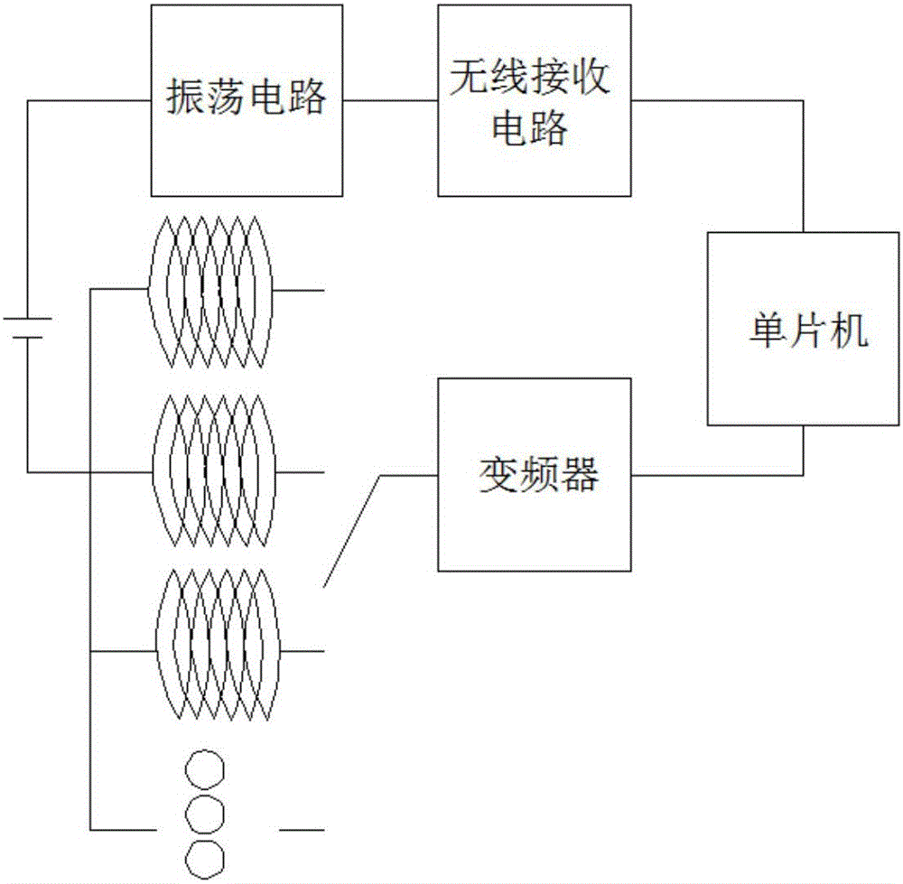
[0057] Three magnetic control structures are respectively arranged inside the upper fin 11, the lower fin 12 and the fish tail 13, and are used to drive the movement of the upper fin 11, the lower fin 12 and the fish tail 13, and then drive the movement of the bionic robot fish ,

[...


PUM


Abstract

The invention belongs to the field of underwater detection and specifically relates to a bionic robotic fish. The bionic robotic fish comprises a shell, an upper fish fin, a lower fish fin, a fish tail, a copper shell, a sealing cover, three magnetic control structures, three electric control structures and a wireless electric remote controller, wherein the upper fish fin is fixedly arranged at the top of the shell; the lower fish fin is fixedly arranged at the bottom of the shell; the fish tail is fixedly arranged at the tail of the shell; the copper shell is arranged in the shell; an external thread is arranged on a side wall at one end of the copper shell; an internal thread which is matched with the external thread of the copper shell is arranged on the inner side of the sealing cover; the sealing cover is connected with the copper shell through the thread; the magnetic control structures are respectively arranged in the upper fish fin, the lower fish fin and the fish tail and are used for driving the upper fish fin, the lower fish fin and the fish tail to move so as to drive the bionic robotic fish to move; the electric control structures are fixedly arranged in the copper shell; the mounting positions of the electric control structures are respectively matched with the positions of the upper fish fin, the lower fish fin and the fish tail; the electric control structures are used for driving the magnetic control structures; the wireless electric remote controller is communicated with the electric control structures and is used for remotely controlling the underwater motion direction and speed of the bionic robotic fish.

Description

technical field [0001] The invention belongs to the field of underwater detection, and in particular relates to a bionic robot fish. Background technique [0002] Water resources are the foundation of human survival. In order to make remote water quality detection or underwater condition detection more convenient, people have invented a series of machines that work underwater. However, the current underwater exploration machines are all directly powered by electric energy, and the pulse current passes through the stepper motor to form a certain angular velocity or linear velocity to drive the rotation of the propeller in the water, and then push the machine to move underwater. Due to the pressure and fluidity of water, this kind of energy supply system is faced with the risk of seal failure caused by friction between the propeller, gear or other rotating parts and the motor structure, resulting in water ingress, electric leakage, engine damage, etc. In order to avoid such R...

Claims


Application Information

Patent Timeline
IPC IPC(8): B63H1/36B63G8/00
CPCB63G8/001B63G2008/002B63H1/36
Inventor 胡军王甜甜王祯何世军
Owner NORTHWEST UNIV
Why Eureka
Try Eureka