
Multi-functional paper-plastic cleaning separation and pulp quenching equipment

A multi-functional, paper-plastic technology, applied in raw material separation, papermaking, paper recycling, etc., can solve the problems of not being able to observe the working conditions of the rectangular buffer cover, external operators being unable to find faults in time, and delaying the timing of emergency shutdown, etc., to achieve Avoid inflexible or stuck rotation, compact structure, and meet the effect of shielding protection

Inactive Publication Date: 2017-02-22
CHONGQING VOLIK ENVIRONMENTAL PROTECTION EQUIP CO LTD
View PDF7 Cites 0 Cited by
  • Summary
  • Abstract
  • Description
  • Claims
  • Application Information

AI Technical Summary

Problems solved by technology

Due to the different cleanliness of different material sources to be processed, this requires that the distance between the outer diameter of the friction strip and the screen should be kept in an adjustable state. However, the current design can only adjust this distance during assembly. After the completion, the distance is fixed, so there is a problem of inconvenient adjustment. When stirring and cleaning some materials with special shapes and sizes, the distance between the axial outer diameter of the friction strip on the main shaft and the screen may be too small. Stuck
On the other hand, the cleaning equipment recorded in this patent cannot observe the working conditions in the rectangular buffer cover during cleaning, and workers cannot effectively monitor the entire cleaning and quenching process. Delay, the external operator cannot find the fault in time, delaying the timing of taking other countermeasures such as emergency shutdown

Method used


Image

  • Multi-functional paper-plastic cleaning separation and pulp quenching equipment
  • Multi-functional paper-plastic cleaning separation and pulp quenching equipment
  • Multi-functional paper-plastic cleaning separation and pulp quenching equipment

Examples


Embodiment Construction

[0037] The implementation of the present invention will be illustrated by specific specific examples below, and those skilled in the art can easily understand other advantages and effects of the present invention from the contents disclosed in this specification.

[0038] Below in conjunction with accompanying drawing and embodiment the present invention will be further described:

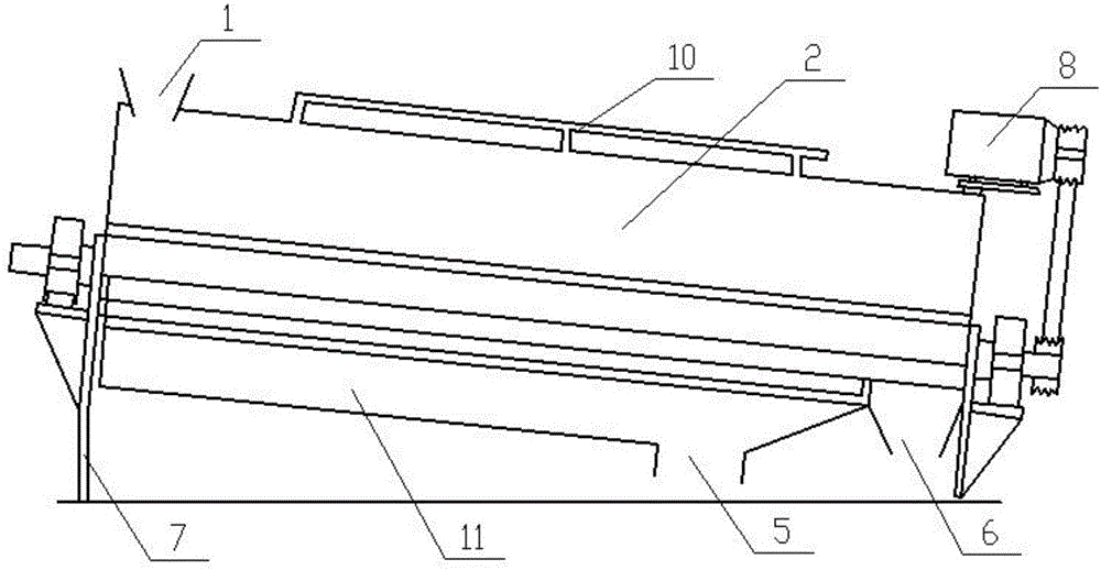
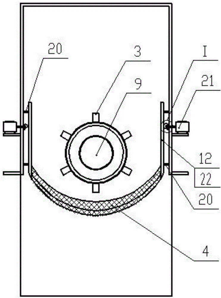
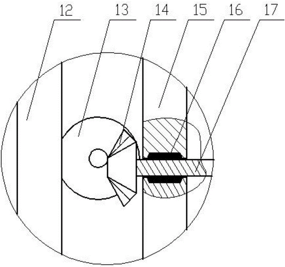
[0039] like figure 1 As shown in -5, a multi-functional paper-plastic cleaning, separating and quenching equipment is composed of a rectangular buffer cover 2 and a semicircular screen 4. The rectangular buffer cover 2 is made into a rectangle, which can prevent excessive feeding and have a buffer space to prevent the spindle 9 stuck. Main shaft 9 runs straight through the machine barrel, and the motor is installed above the rectangular buffer cover 2, and the 9 rotating speeds of the main shaft are regulated with belt pulleys. The friction strip 3 is in the same direction as the main shaft 9, an...


PUM


Abstract

The invention discloses a multi-functional paper-plastic cleaning separation and pulp quenching equipment which comprises a barrel containing a rectangular cushion and a water collecting hood. The feed port is arranged above the barrel, and the discharge port is arranged below. Inside the barrel installed a main shaft with friction blade. The inner part of the water collecting hood is provided with a screen mesh with a vertical steel plate, where the plate is arranged with racks meshing with cylinder wheel gear on the gear shaft, and on the other end of the gear shaft is provided with the second bevel gear in order to mesh with the first bevel gear on the lifting motor. A rectangular buffer hood is provided with a transparent window and an opaque telescopic curtain, the transparent window is symmetrically provided with a chute; the telescopic curtain is composed of a first curtain plate and a second curtain plate, the right side of the first curtain plate is provided with a groove, and the left side of the second curtain plate is formed with protrusion. The main shaft is provided with an optical axis on a partition plate which is composed of a connecting plate and a rectangular plate and an arc plate. The device has the advantages of anti-stuck, and convenient of checking the internal operation of the equipment by adjusting the height of the screen mesh.

Description

technical field [0001] The invention relates to the technical field of waste water garbage treatment, in particular to a paper-plastic separation and quenching equipment in garbage treatment. Background technique [0002] With the improvement of people's awareness of environmental protection and the rapid development of the resource recycling industry, the waste plastics, waste paper packaging, and waste paper and plastic bags produced in people's daily life are no longer directly discarded or incinerated, but are processed by special equipment. Processing can not only recycle plastic resources, but also reuse waste paper. The country's emission standards for paper and plastic manufacturing plants have also been continuously improved, requiring the removal of paper residues and plastic fragments in sewage as much as possible. For example, the invention patent with Chinese patent number 201320734435.X discloses a high-speed friction cleaning, paper-plastic separation, and re...

Claims


Application Information

Patent Timeline
IPC IPC(8): D21D5/02D21B1/32D21B1/02
CPCD21B1/023D21B1/32D21D5/02Y02W30/64
Inventor 陈文
Owner CHONGQING VOLIK ENVIRONMENTAL PROTECTION EQUIP CO LTD
Learn More