Assembled concrete filled steel tubular column splicing structure and method

A technology for concrete-filled steel pipe columns and concrete columns, which is applied in the direction of columns, pier columns, pillars, etc., and can solve the problems of non-compliance with applicable, economical, green, and beautiful architectural guidelines, low recycling rate of building materials, and high material and energy consumption. , to achieve superior energy dissipation capacity and ductility of the overall structure, reduce on-site welding work and template work, and achieve low repair and replacement costs

Inactive Publication Date: 2017-02-22
HUAQIAO UNIVERSITY
4 Cites 5 Cited by

AI-Extracted Technical Summary

Problems solved by technology

[0002] With the rapid development of urbanization in China, the traditional reinforced concrete structure is no longer in line with the "applicable" policy promoted by the state due to its shortcomings such...

Method used

...

Abstract

The invention discloses an assembled concrete filled steel tubular column splicing structure and method. The assembled concrete filled steel tubular column splicing structure comprises prefabricated upper and lower concrete filled steel tubular columns, steel bars are embedded in the upper concrete filled steel tubular columns, and corrugated casing pipes are embedded in the upper concrete filled steel tubular columns. After the reserved corrugated casing pipes are filled with concrete grout in a constructions site, the embedded steel bars in the upper concrete filled steel tubular columns are inserted into the corrugated casing pipes to make the upper concrete filled steel tubular columns arranged on the lower concrete filled steel tubular columns and in butt joint with the lower concrete filled steel tubular columns, and then steel pipe connecting parts are welded to achieve concrete filled steel tubular column splicing. All the members used in the structure are assembled and connected in the site, a site formwork project and welding work are decreased, the industrialized assembling efficiency of a building is improved, and the energy-saving and environmentally friendly building design concept for sustainable development of building members is embodied.

Application Domain

StrutsPillars +1

Technology Topic

Steel tubeRebar +6

Image

  • Assembled concrete filled steel tubular column splicing structure and method
  • Assembled concrete filled steel tubular column splicing structure and method
  • Assembled concrete filled steel tubular column splicing structure and method

Examples

  • Experimental program(1)

Example Embodiment

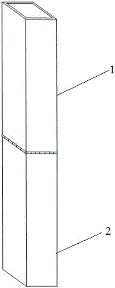
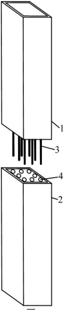
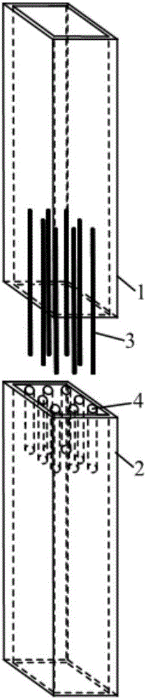
[0029] See Figure 1 to Figure 4 As shown, a splicing structure of a prefabricated concrete-filled steel tubular column and a column includes two concrete-filled steel tubular columns arranged up and down. Several steel bars 3 are embedded in the upper CFST column 1, and part of the steel bars 3 extend downward from the bottom surface of the upper CFST column 1; Lower the top surface of CFST column 2. Concrete slurry is injected into the corrugated casing 4 and the steel bars 3 are inserted into the corrugated casing 4 in one-to-one correspondence, so that the bottom surface of the upper CFST column 1 is connected to the top surface of the lower CFST column 2, and the butt joint parts of the steel pipe are welded at the same time. Realize the splicing of two concrete-filled steel tubular columns.
[0030] The steel bar 3 is arranged parallel to the axis of the upper CFST column 1, the corrugated sleeve 4 is arranged parallel to the axis of the lower CFST column 2, and the upper and lower CFST columns 1 and 2 are coaxially spliced ​​to form a whole.
[0031] The diameter of the steel bar is smaller than the inner diameter of the corrugated sleeve. Specifically, the inner diameter of the corrugated sleeve 4 is 3 to 7 times the diameter of the steel bar 3, and the preferred steel bar 3 is located in the middle of the corrugated sleeve 4 to ensure that the outer circumference of the steel bar 3 The thickness of the concrete is uniform, thereby improve its stability. Through the arrangement of the corrugated sleeve, the reinforcing bars are confined within the corrugated sleeve, and the bonding strength is improved.
[0032] Further, the corrugated sleeves 4 are arranged circumferentially along the cross section of the lower CFST column 2 , and the arrangement shape is consistent with the shape of the cross section of the lower CFST column 2 . For example, if the CFST column is a square column, the four peripheries of the corrugated casing are also arranged in a square shape, so as to ensure uniform force in all directions. The setting of the reinforcement is the same as that of the corrugated casing. In addition, the setting spacing of the corrugated casing should also meet the requirements of relevant specifications and structures to ensure that the shear bearing capacity of the steel bar plays a role.
[0033] Further, the concrete slurry poured into the corrugated casing is non-shrinkage self-compacting high-strength concrete, and the strength grade is not lower than that of the concrete-filled steel tube column.
[0034] The splicing method of the above-mentioned splicing structure, comprises the following steps:
[0035] 1) Provide the upper CFST column prefabricated parts and the lower CFST column prefabricated parts. The upper CFST column prefabricated parts include the upper CFST column 1 and the steel bars 3 embedded in the upper CFST column. The lower CFST column prefabricated parts include the lower CFST column. CFST column 2 and corrugated casing 4 pre-buried in the lower CFST column;
[0036] 2) The prefabricated concrete-filled steel tubular column is fixed in place at the construction site, and concrete grouting is performed on the corrugated casing 4;
[0037] 3) the upper CFST column prefab is placed on the lower CFST column prefab and the reinforcing bars 3 are inserted into the corrugated casing 4 in one-to-one correspondence, so that the bottom surface of the upper CFST column is in contact with the top surface of the lower CFST column;
[0038] 4) Weld the butt joints of the steel pipes of the upper CFST column 1 and the lower CFST column 2 to make them integral.
[0039] Among them, the prefabricated part of the upper CFST column and the prefabricated lower CFST column can be processed in the factory, and the splicing step can be implemented on the construction site. The manufacturing method of the prefabricated part of the lower CFST column is as follows: according to the design requirements, the steel pipe is provided, a number of corrugated sleeves are arranged in the steel pipe parallel to the axis of the steel pipe, and one end of the corrugated sleeve is flush with one end of the steel pipe, and the corrugated sleeve is placed in the steel pipe. Concrete slurry is injected into the area outside the pipe to form a concrete-filled steel tubular column while the corrugated casing is fixed. The manufacturing method of the prefabricated part of the upper CFST column is as follows: according to the design requirements, the steel pipe is provided, a number of steel bars are arranged in the steel pipe parallel to the axis of the steel pipe, and each steel bar part extends out of the steel pipe, and the arrangement position of the steel bar is the same as that of the corrugated sleeve. Corresponding to the pipes, concrete slurry is injected into the steel pipes to form CFST columns and the steel bars are fixed at the same time.
[0040] The prefabricated parts of the upper CFST column and the lower CFST column can be mass-produced in the factory through the assembly line. In this embodiment, the splicing of two CFST prefabricated parts is taken as an example for description. Those skilled in the art know that each CFST column prefabricated part can be provided with corrugated casing at the upper part and steel bars at the lower part at the same time, so as to realize continuous multi-column splicing.
[0041] Further, the upper and lower CFST columns can be connected by groove welding to form a whole, leaving V-shaped grooves at each interface, and welding at the interface after insertion, and the strength of the weld is not lower than the strength of the steel pipe itself.
[0042]The above-mentioned embodiments are only used to further illustrate the splicing structure and method of a prefabricated concrete-filled steel tubular column and a column of the present invention, but the present invention is not limited to the embodiments, and any modifications made to the above embodiments according to the technical essence of the present invention are not limited to the present invention. Simple modifications, equivalent changes and modifications all fall within the protection scope of the technical solutions of the present invention.

PUM

no PUM

Description & Claims & Application Information

We can also present the details of the Description, Claims and Application information to help users get a comprehensive understanding of the technical details of the patent, such as background art, summary of invention, brief description of drawings, description of embodiments, and other original content. On the other hand, users can also determine the specific scope of protection of the technology through the list of claims; as well as understand the changes in the life cycle of the technology with the presentation of the patent timeline. Login to view more.

Similar technology patents

Concrete pouring chute for deep foundation pit

Owner:NO 5 ENG CO LTD OF CCCC FIRST HARBOR ENG

Vertical sliding device for displacement one-way control

ActiveCN111734136AGuarantee the construction qualityGuaranteed smooth progress
Owner:SHANGHAI CONSTRUCTION GROUP +1

Classification and recommendation of technical efficacy words

Why Eureka
Try Eureka