Cooling bed lifting hydraulic synchronous control device

A hydraulic synchronization and control device technology, which is applied in the direction of fluid pressure actuators, cooling beds, metal rolling, etc., can solve the problems of reduced motor life, unstable cooling bed movement, and large pressure drop of synchronous motors, etc., to achieve stable Start and stop, low cleanliness requirements, and small pressure drop at the valve port

Inactive Publication Date: 2017-02-22
CHINA NAT HEAVY MACHINERY RES INSTCO
View PDF6 Cites 5 Cited by
  • Summary
  • Abstract
  • Description
  • Claims
  • Application Information

AI Technical Summary

Problems solved by technology

For example, the lifting of the cooling bed adopts electromagnetic reversing valve and one-way throttle valve, and the four lifting hydraulic cylinders are controlled synchronously through 4 electromagnetic reversing valves and 4 one-way throttle valves respectively. When the partial load of the cooling bed is large, the single The synchronous performance of throttle valve control is very poor, and the operation impact is large, which may easily cause unstable movement of the cooling bed and deformation of the cooling bed body
For example, proportional directional valves and synchronous motors are used to lift the cooling bed, and the four lifting hydraulic cylinders are controlled synchronously through a proportional directional valve and a synchronous motor. With the increase of pulling speed, the operating frequency is gradually accelerated, and the frequency of synchronous motor switching between positive and negative rotation is also accelerated, which reduces the service life of the motor, and the pressure drop of the synchronous motor itself is large, which easily causes the hydraulic system to heat up

Method used


Image

  • Cooling bed lifting hydraulic synchronous control device

Examples


Embodiment Construction

[0018] The present invention will be further described in detail below in conjunction with specific embodiments, which are explanations of the present invention rather than limitations.

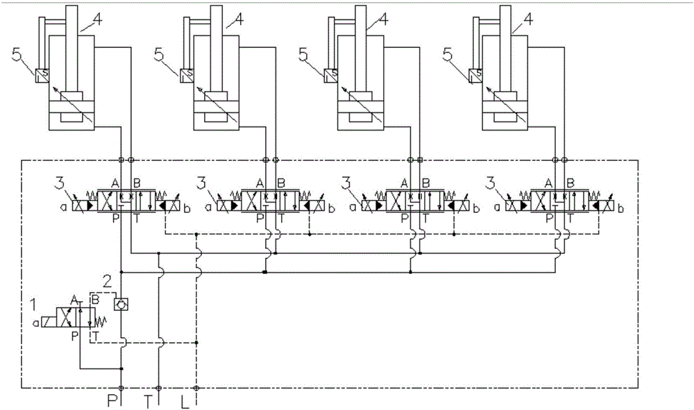
[0019] see figure 1 , a cooling bed lifting hydraulic synchronous control device, including a number of proportional directional valves 3 arranged in parallel on the hydraulic valve table next to the cooling bed, and an electromagnetic reversing valve 1 and Hydraulic control check valve 2, servo hydraulic cylinder 4 is also connected to the oil outlet pipeline of each proportional directional valve 3, displacement sensor 5 is set on the servo hydraulic cylinder 4 as an external displacement sensor, displacement sensor 5 is also connected with proportional directional valve 3 connected, the proportional directional valve 3 and the displacement sensor 5 form a position closed loop.

[0020] Among them, the electromagnetic reversing valve 1 controls the oil supply of each proportional direction...


PUM


Abstract

The invention discloses a cooling bed lifting hydraulic synchronous control device. The device comprises a plurality of proportional direction valves arranged on hydraulic valve stand beside a cooling bed in parallel, an electromagnetic reversing valve and a hydraulic control check valve are arranged on a communication pipeline of the proportional direction valves and hydraulic oil, an oil outlet pipeline of each proportional direction valve is further connected with a servo hydraulic cylinder, displacement sensors serving as external displacement sensors are arranged on the servo hydraulic cylinders, the displacement sensors are also connected with the proportional direction valves, and the proportional direction valves and the displacement sensors form position closed loops. Closed-loop control precision of cooling bed lifting hydraulic synchronous control can reach +/-1 mm; compared with existing cooling bed lifting control schemes, synchronous control precision is very high, and synchronous control precision can also be guaranteed especially when unbalance loading of the cooling bed is large; by setting a curve of proportional direction valve control signals, stable start and shutdown are easy to achieve, and quick lifting operation is achieved.

Description

technical field [0001] The invention belongs to the technical field of metallurgical equipment, and relates to a hydraulic synchronous control device for lifting and lowering a cooling bed. Background technique [0002] The cooling bed is one of the important equipment on the production line of the square (round) billet continuous casting machine. In order to ensure the cooling quality of the casting billet, a stepping cooling bed is generally used; gradually cooled during the transfer. Since the slab is cut into lengths ranging from 6m to 12m according to needs, this increases the degree of eccentric load during the lifting operation of the cooling bed; when the casting machine just starts production, the slab on the cooling bed increases gradually, and the load on the cooling bed increases from The upper cooling bed side of the slab gradually increases, or the cooling bed slab gradually decreases at the end of production, and the load of the cooling bed gradually decrease...

Claims


Application Information

Patent Timeline
Patent Type & Authority Applications(China)
IPC IPC(8): F15B9/09F15B13/08F15B13/16B21B43/00
CPCF15B9/09B21B43/00F15B13/08F15B13/16
Inventor 李向辉张伟李生斌
Owner CHINA NAT HEAVY MACHINERY RES INSTCO
Why Eureka
Try Eureka