Blast furnace top material flow regulation control system and method

A control system and flow adjustment technology, applied in the field of blast furnace smelting, can solve the problems of uneven distribution, large impact, and increased equipment failures, and achieve the effect of improving safety, uniform distribution, and uniform distribution

Active Publication Date: 2022-04-29
SINOSTEEL XIAN MACHINERY
View PDF6 Cites 0 Cited by
  • Summary
  • Abstract
  • Description
  • Claims
  • Application Information

AI Technical Summary

Problems solved by technology

[0003] The material flow of the blast furnace is controlled by the material flow regulating valve. At present, more control methods are used to control the oil cylinder of the regulating valve through hydraulic pressure, so as to control the size of the material flow. The conventional material flow regulating valve control system uses solenoid valves or proportional valves. The valve is controlled, and its control loop structure is as follows figure 1 As shown, it is mainly composed of one-way valve, electromagnetic reversing valve, hydraulic lock, throttle valve, ball valve, integrated valve block and ball valve, etc., and has the following disadvantages: ① poor precision, and the control precision is low when using electromagnetic valve; ② the speed cannot Continuous adjustment, the speed of the oil cylinder can only be adjusted manually, and cannot be continuously controlled; ③The material distribution is uneven, and the poor accuracy of the material flow adjustment leads to uneven distribution, and there is a phenomenon of under-distribution or excessive distribution; ④Poor safety, unable to automatically switch when the hydraulic circuit fails ;⑤The impact is large, and the constant speed control causes a large impact when the equipment starts and stops; ⑥Energy waste, low precision of cloth control leads to waste of raw materials; Combustion causes a large amount of combustion gas emissions; ⑧ Difficult maintenance, unable to maintain online; ⑨ High failure rate, large impact, large vibration, and high temperature lead to increased equipment failures

Method used


Image

  • Blast furnace top material flow regulation control system and method
  • Blast furnace top material flow regulation control system and method

Examples


Embodiment Construction

[0046] Reference will now be made in detail to the exemplary embodiments, examples of which are illustrated in the accompanying drawings. When the following description refers to the accompanying drawings, the same numerals in different drawings refer to the same or similar elements unless otherwise indicated. The implementations described in the following exemplary examples do not represent all implementations consistent with the present invention. Rather, they are merely examples of arrangements consistent with aspects of the invention as recited in the appended claims.

[0047] In order to enable those skilled in the art to better understand the technical solutions of the present invention, the present invention will be further described in detail below in conjunction with the accompanying drawings and embodiments.

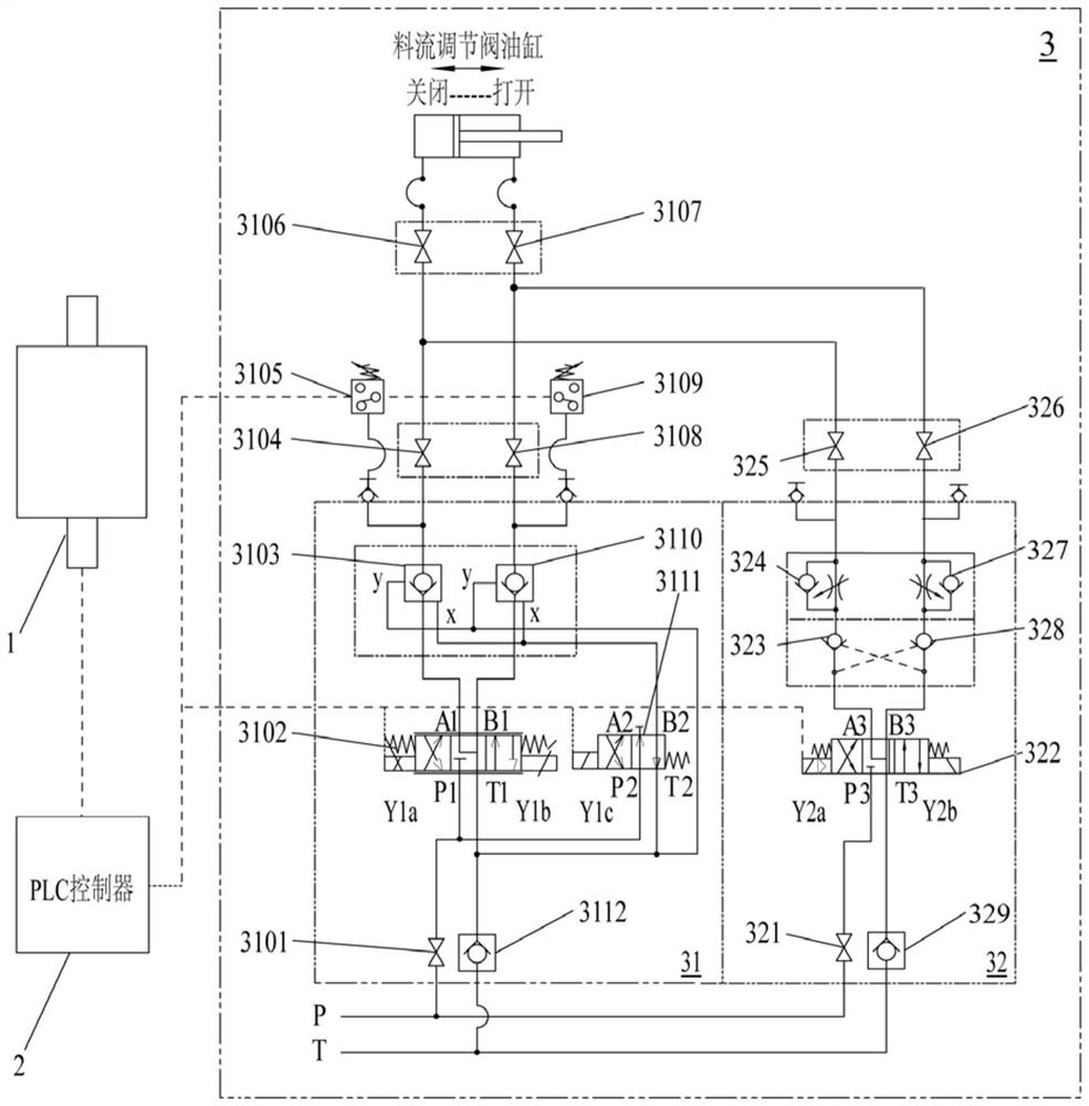
[0048] See figure 2 As shown, a blast furnace top material flow regulation control system of the present invention includes a detection encoder 1, a PLC con...


PUM


Abstract

The invention discloses a blast furnace top material flow regulation control system and method, the blast furnace top material flow regulation control system comprises a detection encoder, a PLC controller and a hydraulic control loop, the PLC controller is connected with the detection encoder and the hydraulic control loop, the PLC controller sends a control signal to the hydraulic control loop after calculation to control the speed and position of an oil cylinder, and the hydraulic control loop is connected with the detection encoder. The detection encoder detects and calibrates the position of the oil cylinder and inputs the position to the PLC, and the PLC performs correction control on the hydraulic control loop after calculation according to detection data of the detection encoder, so that closed-loop control is formed, the precision of material flow regulation control is smaller than 0.2 degree, the hydraulic control loop comprises a main loop and a standby loop, and the standby loop is connected with the main loop. And switching can be carried out through the PLC. The method has the advantages of high control precision, good safety, automatic adjustment, energy conservation and the like, the failure rate in the blast furnace cloth smelting process can be reduced, the working efficiency of furnace top cloth operation is improved, and the service life of equipment is prolonged.

Description

technical field [0001] The invention belongs to the technical field of blast furnace smelting, and in particular relates to a blast furnace top material flow regulation control system and method. Background technique [0002] As we all know, in the blast furnace production process, the control of the opening of the material flow regulating valve is very important. Only when the actual opening is controlled accurately enough can the material distribution flow of the blanking gate be effectively controlled, so that the furnace material can be controlled according to the angle set by the material distribution matrix. The position, number of parts and material distribution time are accurately distributed to the furnace material surface, so that the top material distribution and upper part adjustment can be realized accurately and efficiently, and the stable operation of the blast furnace production can be ensured. [0003] The material flow of the blast furnace is controlled by ...

Claims


Application Information

Patent Timeline
Patent Type & Authority Applications(China)
IPC IPC(8): C21B7/20C21B7/24C21B5/00
CPCC21B7/20C21B7/24C21B5/006
Inventor 同国庆马小龙回广振
Owner SINOSTEEL XIAN MACHINERY
Why Eureka
Try Eureka