An air separation cold box panel enclosure structure

An enclosure structure and cold box technology, applied in pipeline protection, cold treatment separation, refrigeration and liquefaction, etc., can solve problems such as unreliable structural safety and economics, inconvenient calculation results, and damage to the stress system of the main structure. Review, simple and accurate calculation, and the effect of reducing steel consumption

Active Publication Date: 2018-03-23
盈德气体工程(浙江)有限公司
View PDF5 Cites 0 Cited by
  • Summary
  • Abstract
  • Description
  • Claims
  • Application Information

AI Technical Summary

Problems solved by technology

[0002] The traditional air separation cold box adopts a plate structure system. This structure divides the entire cold box into dozens or even hundreds of plate units. Each unit is made of H-shaped steel or channel steel as an edge member, including diagonal braces and Panel, when each unit is connected, the edge member and the edge member are connected by bolts and welding to form a new member, that is, a beam or a column; the diagonal brace is made of H-shaped steel, and the panel is directly welded on the diagonal brace, usually without a panel Stiffeners, even if the panel stiffeners are individually set, the stiffeners are welded together on the diagonal braces, causing the diagonal braces to bear huge out-of-plane loads from the panels, including pearlescent sand loads on the panels, nitrogen pressure and cold box panels. Wind load suction or pressure, which destroys the original truss structure system of the main structure, because the diagonal brace of the truss structure system is a two-force rod, which does not bear the load outside the plane; and the special structure of the cold box is hollow and has no floors. For slabs, the load is mainly transmitted by the surrounding truss structures. Once the stress mode of the diagonal bracing members of the truss structure system is changed from a two-force bar to a tension-compression shear-bend member, the load transmission path of the entire structural system will be unclear. , it is inconvenient to manually review the calculation results of the software with engineers, and the safety and economics of the structure are not reliable, which leads many engineers to blindly believe in the results of the software, resulting in many safety accidents and immeasurable economic losses
[0003] The existing air separation cold box structure system and panel enclosure system are not disengaged, which not only damages the stress system of the main structure, but also usually does not set stiffeners, and only relies on beams, columns and diagonal braces as the support of the panel. Although relatively thick 5mm steel plates are used for the panels around the cold box, when the wind load is large or the panel span is large, the strength will be insufficient, resulting in the bursting of the cold box panel, and the pearlescent sand insulation material in the cold box is sprayed out. Occurs from time to time, causing the entire air separation system to be shut down for maintenance, resulting in huge direct and indirect economic losses, and sometimes even casualties
[0004] To sum up, if the diagonal bracing and panel enclosure system of the traditional air separation cold box structure system are not disengaged, it is very unfavorable to the main structural system and panel enclosure system, and a new design method is urgently needed to optimize it.

Method used


Image

  • An air separation cold box panel enclosure structure
  • An air separation cold box panel enclosure structure
  • An air separation cold box panel enclosure structure

Examples


Embodiment Construction

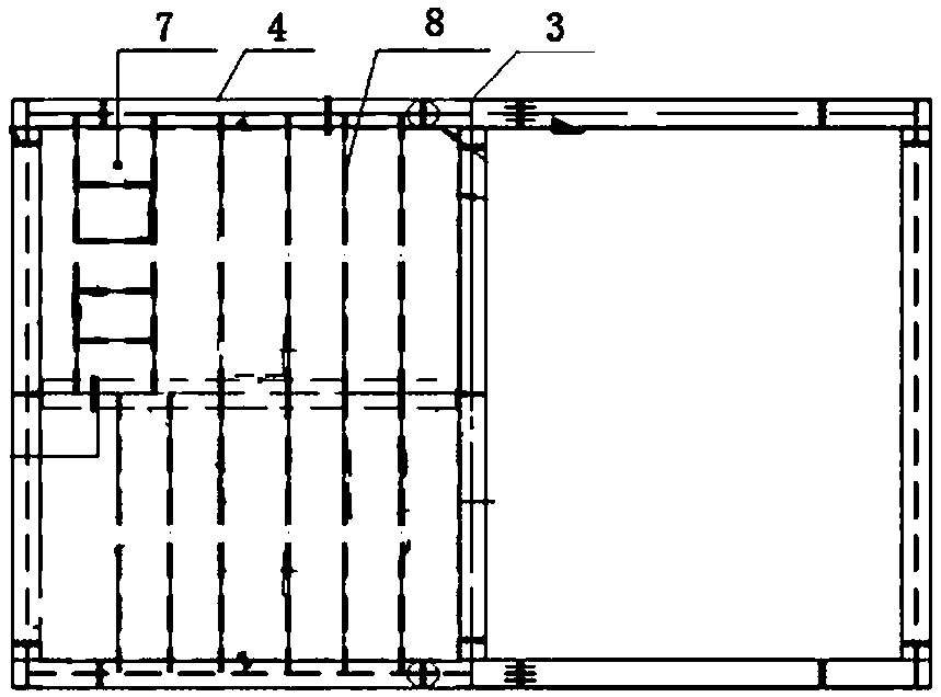
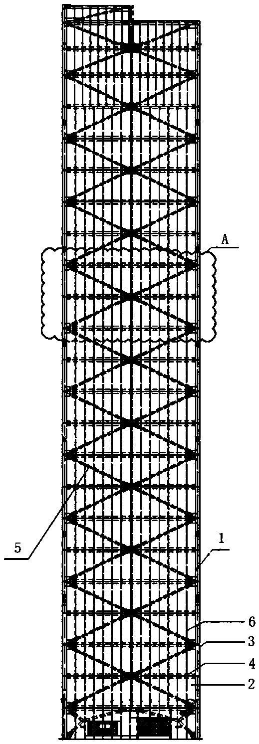
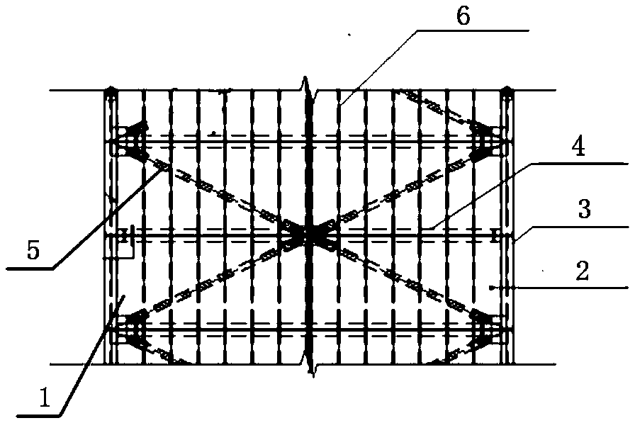
[0016] The present invention will be described in detail below in conjunction with the drawings: Figure 1-3 As shown, an air separation cold box panel enclosure structure according to the present invention is mainly composed of a surrounding truss structure 1 and a cold box panel 2 enclosed on the surrounding truss structure 1, so The truss structure 1 described is composed of long cold box columns 3 on both sides, a plurality of cold box beams 4 fixed on the cold box columns 3 on both sides in turn, and three cold box beams 4 cross-fixed from top to bottom. The box beam 4 is composed of two diagonal braces 5 with the middle of the middle cold box beam as the crossing point. The truss structure 1 is vertically fixed on the cold box beam 4 and horizontally distributed on the cold box beam 4 A plurality of stiffening ribs 6 extending from the bottom to the top; the truss structure 1 is respectively sealed and welded with cold box panels 2 for wrapping the entire cold box.

[0017...


PUM


Abstract

Provided is a panel enclosing structure for an air-separation cold box. The air-separation cold box is mainly composed of surrounding truss structures and cold box panels enclosing the surrounding truss structures, and each truss structure is composed of long cold box columns on the two sides, multiple cold box cross beams and two inclined struts, wherein the cold box cross beams are sequentially fixed to the cold box columns on the two sides in an up-and-down mode, the two inclined struts are sequentially fixed to the upper cold box cross beam, the middle cold box cross beam and the lower cold box cross beam in a crossed mode from top to bottom, and the middle of the middle cold box cross beam serves as a cross point of the two inclined struts; the truss structures are vertically fixed to the cold box cross beams, and multiple stiffening ribs which extend to the top from the bottom are horizontally and evenly distributed on the cold box cross beams. Cold box panels used for wrapping the whole cold box are welded to each truss structure in a sealed mode; according to connection between the cold box panels and the cold box columns and the cold box cross beams, the overlapping length, reserved on the outer side faces of the cold box columns and the cold box cross beams, of the cold box panels is 30 mm or above, 4-cm fillet weld all-around welding, namely sealing welding is adopted at outer overlapping joints for avoiding air leakage, and 4-cm fillet weld intermittent welding is adopted at inner overlapping joints.

Description

Technical field [0001] The invention relates to an air separation cold box panel enclosure structure, which is suitable for air separation oxygen and nitrogen production equipment cold boxes, argon production equipment cold boxes, hydrogen production equipment cold boxes, heat exchanger cold boxes and liquefaction equipment cold boxes, etc. All enclosed cold boxes containing cryogenic equipment belong to the field of air separation refrigeration technology. Background technique [0002] The traditional air separation cold box adopts a plate structure system. This structure divides the entire cold box into dozens or even hundreds of plate units. Each unit is made of H-shaped steel or channel steel as the edge member, including diagonal braces and For the panel, when each unit is connected, the edge member and the edge member are connected by bolts and welding to form a new member, that is, a beam or a column; the diagonal brace is made of H-shaped steel, and the panel is directly ...

Claims


Application Information

Patent Timeline
Patent Type & Authority Patents(China)
IPC IPC(8): F16L59/00
CPCF16L59/00F25J3/04945F25J2290/42
Inventor 吴正军郑少栋彭德龙徐根柱李妍毛炜胡莉丽
Owner 盈德气体工程(浙江)有限公司
Why Eureka
Try Eureka