Non-contact type fiber ultrasonic sensor
An ultrasonic sensor, non-contact technology, applied in the field of sensors, can solve problems such as difficult to correctly obtain discharge signals, electrical pulse signal interference, etc., and achieve good response characteristics and high spectral signal-to-noise ratio
- Summary
- Abstract
- Description
- Claims
- Application Information
AI Technical Summary
Problems solved by technology
Method used
Image

Examples
Embodiment 1
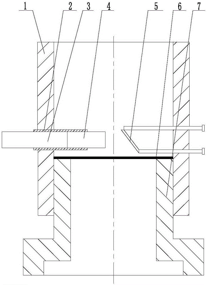
[0019] exist figure 1 Among them, the non-contact optical fiber ultrasonic sensor of this embodiment is composed of an optical fiber mounting ring 1, an optical fiber fixing tube 2, a single-mode optical fiber 3, an optical fiber collimating mirror 4, a reflecting mirror 5, a sensing film 6, and a hollow plug 7.
[0020] The shape of the optical fiber installation ring 1 is a ring body. In the central plane of the height of the side wall of the optical fiber installation ring 1, an optical fiber fixing tube 2 is installed radially on the left side through threaded connection, and a single-mode optical fiber 3 and an optical fiber Collimating mirror 4, the center line of single-mode optical fiber 3 and fiber collimating mirror 4 coincide, the length of the fiber collimating mirror 4 of the present embodiment is 8mm, the wavelength of fiber collimating mirror 4 is 1560nm, and the fiber collimating mirror 4 A transflective film with a light transmittance of 50% is vacuum-evaporat...
Embodiment 2
[0022] In the central plane of the side wall height of the optical fiber installation ring 1, an optical fiber fixing tube 2 is mounted radially on the left side through threaded connection, and a single-mode optical fiber 3 and an optical fiber collimator 4 are installed in the optical fiber fixing tube 2, and the single-mode optical fiber 3 and the optical fiber The centerlines of the collimator mirror 4 coincide, the length of the collimator mirror 4 is 5mm, the wavelength of the collimator mirror 4 is 1560nm, the right end surface of the collimator mirror 4 is vacuum-deposited with a light transmittance of 50%. The semi-transparent and semi-reflective film, the single-mode optical fiber 3 is clamped on the optical fiber fixing tube 2, and the right end of the single-mode optical fiber 3 is bonded to the left end surface of the optical fiber collimator 4 with optical glue. In the central plane of the height of the inner wall of the optical fiber installation ring 1, the radi...
Embodiment 3
[0025] In the central plane of the side wall height of the optical fiber installation ring 1, an optical fiber fixing tube 2 is mounted radially on the left side through threaded connection, and a single-mode optical fiber 3 and an optical fiber collimator 4 are installed in the optical fiber fixing tube 2, and the single-mode optical fiber 3 and the optical fiber The centerlines of the collimator mirror 4 coincide, the length of the collimator mirror 4 is 10mm, the wavelength of the collimator mirror 4 is 1560nm, the right end surface of the collimator mirror 4 is vacuum-deposited with a light transmittance of 50%. The semi-transparent and semi-reflective film, the single-mode optical fiber 3 is clamped on the optical fiber fixing tube 2, and the right end of the single-mode optical fiber 3 is bonded to the left end surface of the optical fiber collimator 4 with optical glue. In the central plane of the height of the inner wall of the optical fiber installation ring 1, the rad...
PUM
| Property | Measurement | Unit |
|---|---|---|
| Thickness | aaaaa | aaaaa |
| Length | aaaaa | aaaaa |
| Wavelength | aaaaa | aaaaa |
Abstract
Description
Claims
Application Information
PatSnap Eureka turns technology decisions into work you can execute. Powered by our Innovation Knowledge Graph, it runs expert workflows across engineering, life sciences, materials and intellectual property. Get your review-ready output in minutes.


