Optical Analog-to-Digital Converter with Configurable Frequency Response

A frequency response, digital conversion technology, applied in optical analog/digital converters, optics, instruments, etc., can solve problems such as inability to simultaneously realize, noise, and system complexity, to reduce complexity, reduce requirements, and improve flexibility. Effect

Active Publication Date: 2019-02-01
SHANGHAI JIAOTONG UNIV
View PDF6 Cites 0 Cited by
  • Summary
  • Abstract
  • Description
  • Claims
  • Application Information

AI Technical Summary

Problems solved by technology

The currently reported microwave photonic filtering and optical analog-to-digital conversion schemes can only perform one of the functions of filtering or analog-to-digital conversion, and the two cannot be directly connected in the optical domain to achieve two functions at the same time
If connected by photoelectric conversion, not only the system is complicated, but also additional noise will be introduced

Method used


Image

  • Optical Analog-to-Digital Converter with Configurable Frequency Response
  • Optical Analog-to-Digital Converter with Configurable Frequency Response
  • Optical Analog-to-Digital Converter with Configurable Frequency Response

Examples


Embodiment 1

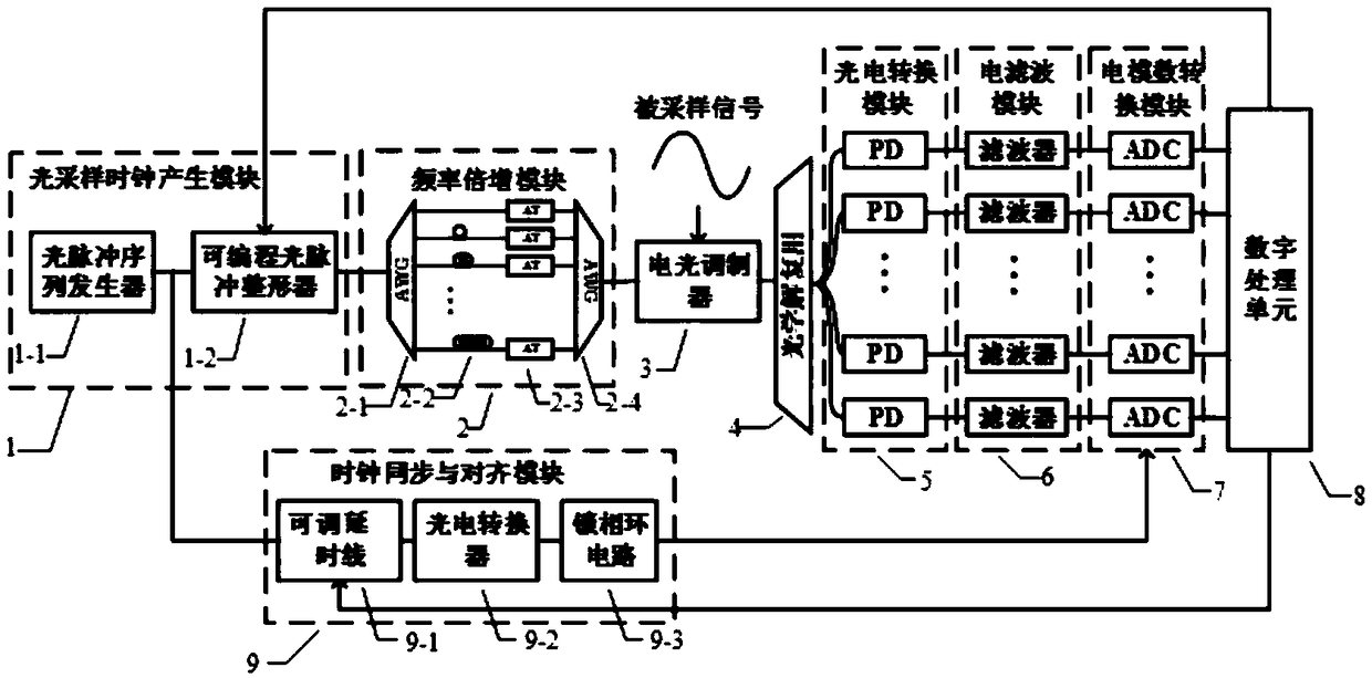
[0025] The system block diagram of this embodiment is as follows figure 1 As shown, it includes: optical sampling clock generation module 1, repetition frequency multiplication module 2, electro-optical modulator 3, optical demultiplexer 4, photoelectric conversion module 5, electrical filter module 6, electrical analog-to-digital conversion module 7, and digital processing unit 8 and a clock synchronization and alignment module 9.

[0026]The optical sampling clock generating module 1 includes an optical pulse sequence generator (mode-locked laser) 1-1 and a programmable optical pulse shaper (wave shaper, Finisar, 4000s) 1-2. The optical pulse sequence generator 1-1 generates an optical pulse sequence with a repetition frequency f, and sends it to the input terminal of the programmable optical pulse shaper 1-2. Programmable optical pulse shaper 1-2 according to different needs, under the condition that the time-domain width of the impulse response of the electric filter is g...

Embodiment 2

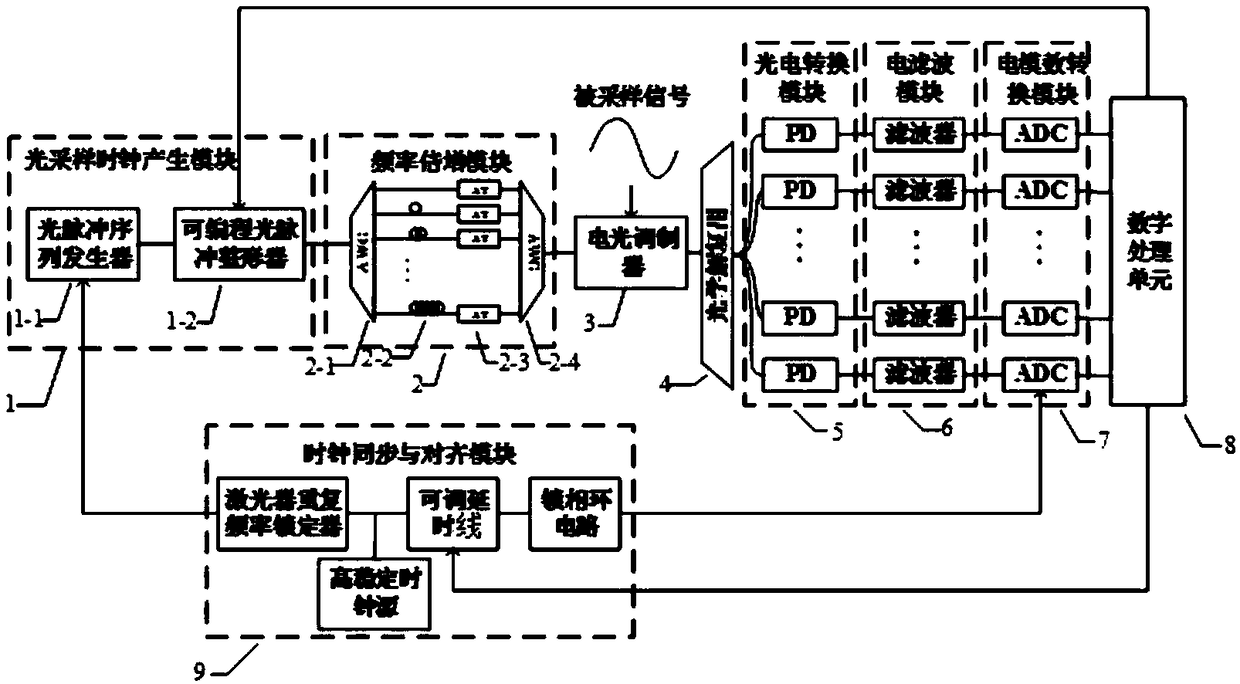
[0035] The system block diagram of this embodiment is as follows image 3 As shown, it includes: optical sampling clock generation module 1, repetition frequency multiplication module 2, electro-optical modulator 3, optical demultiplexer 4, photoelectric conversion module 5, electrical filter module 6, electrical analog-to-digital conversion module 7, and digital processing unit 8, and a clock synchronization and alignment module 9.

[0036] Modules 1-8 in Embodiment 2 are completely the same as those in Embodiment 1 and will not be repeated here.

[0037] The clock synchronization and alignment module 9, such as image 3 As shown, it includes a highly stable clock source, a laser repetition rate locker, an adjustable delay line and a phase-locked loop circuit. A high-stable clock source provides a clock signal with low phase noise and low jitter; after the clock signal passes through the laser repetition rate locker, it is input to the optical pulse sequence generator 1-1 t...


PUM


Abstract

An optical analog-digital converter with configurable frequency response sequentially comprises a controllable pulse shape optical sampling clock generating module, a repetition frequency doubling module, an electro-optical modulator, a multi-channel module, a photoelectric conversion module, an electric filter module, an electric analog-digital conversion module, a digital processing unit and a clock synchronization and aligning module. The optical analog-digital converter with configurable frequency response provides both analog processing and digitalization for broadband input microwave signals, system complexity is greatly reduced, and the problems, such as high insertion loss and signal distortion, due to respective filtration and sampling are avoided; system equivalent frequency response may be configured flexibly by adjusting time-domain shape of an optical sampling clock.

Description

technical field [0001] The invention relates to optical analog-to-digital conversion, in particular to an optical analog-to-digital conversion device with configurable frequency response. Background technique [0002] Due to the limitation of "electronic bottleneck", electronic technology has been difficult to meet the increasingly higher frequency and bandwidth signal processing requirements in the fields of ultra-wideband communication, radar, high-end instruments and scientific research. Photon technology has the advantages of ultra-broadband, ultra-high speed, and high precision, and can effectively overcome the shortcomings of electronic technology. High-frequency broadband signal processing based on photonic technology is currently the focus of attention. [0003] Analog filtering can achieve the purpose of signal frequency selection, phase shift and delay, etc., and is one of the basic analog signal processing technologies. Due to the influence of "electronic bottle...

Claims


Application Information

Patent Timeline
Patent Type & Authority Patents(China)
IPC IPC(8): G02F7/00
CPCG02F7/00
Inventor 王思同吴龟灵金钲韬苏斐然陈建平
Owner SHANGHAI JIAOTONG UNIV
Why Eureka
Try Eureka