A Wind-Induced Vibration Energy Harvester Based on Multi-Cylinder Wake Excitation

An energy harvester and wind-induced vibration technology, which is applied in the direction of piezoelectric effect/electrostrictive or magnetostrictive motors, generators/motors, electrical components, etc., can solve the problem of high wind speed and rigidity requirements for vibration, and achieve improved Effects of energy collection efficiency, improvement of utilization rate, and guarantee of disassembly

Active Publication Date: 2018-08-17
SHANGHAI UNIV
View PDF4 Cites 0 Cited by
  • Summary
  • Abstract
  • Description
  • Claims
  • Application Information

AI Technical Summary

Problems solved by technology

In addition, the nonlinearity of the structure will limit the amplitude to a limited range, so the wind energy harvester based on the flutter mechanism has higher requirements on the starting wind speed and the rigidity of the structure

Method used


Image

  • A Wind-Induced Vibration Energy Harvester Based on Multi-Cylinder Wake Excitation
  • A Wind-Induced Vibration Energy Harvester Based on Multi-Cylinder Wake Excitation
  • A Wind-Induced Vibration Energy Harvester Based on Multi-Cylinder Wake Excitation

Examples


Embodiment 1

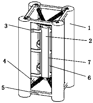
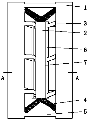
[0027] refer to figure 1 , figure 2 and Figure 5 , in order to solve the problems of the existing wind-induced vibration piezoelectric generator with complex structure, low output voltage, low power density, and single flow direction, the present invention provides a wind-induced vibration energy harvester based on multi-cylindrical wake excitation, It includes an external frame column 1, a central column 2, a piezoelectric transducer 3, a contact spring 4, and a frame rod 5; the external frame column 1 is not less than three, and the frame rod 5 connects the upper end of the external frame column 1 and the The lower ends are fixedly connected in pairs to form a cubic external frame structure; the central column 2 is located at the geometric center of the cubic external frame structure, and the central column 2 is arranged in parallel with the external frame column 1, and the central column 2 is slightly shorter than the external frame column 1; One end of the contact spri...

Embodiment 2

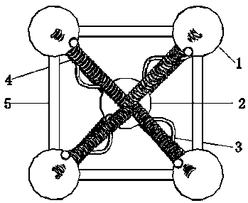
[0033]The difference from the above embodiment is that the number of fixed piezoelectric transducers 3 between the central column 2 and the outer frame column 1 changes; the piezoelectric transducers 3 are not necessarily along the four diagonal directions. Limited to 1, but could be 2 or 3. Its characteristic is that the wind load acts on the outer frame column 1, forming a Karman vortex street in the wake, and the vortex street acts on the central cylinder 2, causing the wake excitation of the central cylinder 2 to drive the deformation of the piezoelectric transducer 3 and output voltage . At the same time, the connection between the central column 2 and the outer frame column 1 changes as the number of piezoelectric transducers 3 changes.

Embodiment 3

[0035] The difference from the above-mentioned embodiments is that the cross-sectional shape of the thin rod 6 fixedly connected with the piezoelectric transducer 3 can be circular, rectangular or trapezoidal. Corresponding parts of the central column 2 and the outer frame column 1 reserve a through groove 7 consistent with the size of the thin rod 6 for fixing the thin rod 6 . Its characteristic is that the thin rod 6 fixedly connected with the piezoelectric transducer 3 can be well combined with the central cylinder 2 and the outer frame column 1 under the premise of not changing the outer surface shape of the central cylinder 2 as much as possible, and the piezoelectric transducer 3. Minimize the impact on the central cylinder 2 external wind field.


PUM


Abstract

The invention relates to wind-induced vibration energy collectors, in particular to a wind-induced vibration energy collector based on multi-cylinder wake excitation. The wind-induced vibration energy collector is applicable to low-power electronic equipment such as a sensor which needs to acquire energy from an external environment and comprises external frame columns, a central cylinder, piezoelectric transducers, connecting springs and frame rods. The wind-induced vibration energy collector is characterized in that wind load in an environment acts on the external frame columns, airflow is separated on the surfaces of the external frame columns and generates alternating-falling vortexes at the tails of the external frame column, the central cylinder vibrates under the action of the wake of the frame columns, the vibration of the cylinder drives arc-shaped metal sheets to deform, and piezoelectric elements adhered to the arc-shaped metal sheets deform and polarize to externally output voltage. The wind-induced vibration energy collector has the advantages that the wind energy collector formed by the internal central cylinder and the external frame columns surrounding the central cylinder is simple and compact in structure, easy in encapsulation, capable of collecting the wind energy of different wind speeds and different wind directions, and capable of greatly increasing energy utilization rate and collector output power.

Description

technical field [0001] The invention relates to a wind-induced vibration energy harvester, in particular to a wind-induced vibration energy harvester based on multi-cylinder wake excitation, which is suitable for sensors and other low-power electronic devices that need to obtain energy from the external environment. Background technique [0002] With the development of micro-electromechanical systems, the sensor nodes used in wireless sensor networks have gradually attracted people's attention, and have a wide range of application requirements in military and civilian fields such as transportation, medical care, information, environment, aerospace, etc., and have become a research hotspot at home and abroad. . Due to the large number of nodes in the wireless sensor network, the wide distribution area, the harsh working environment, and the long working cycle, traditional chemical batteries have problems such as large size, short life, and low power density, which have become...

Claims


Application Information

Patent Timeline
Patent Type & Authority Patents(China)
IPC IPC(8): H02N2/18
CPCH02N2/185
Inventor 杜晓庆周杨张盛华周志豪宗振邦卢慧张洋
Owner SHANGHAI UNIV
Why Eureka
Try Eureka